
Substrate housing container

a technology for substrates and containers, applied in the direction of electrical apparatus casings/cabinets/drawers, electrical apparatus construction details, transportation and packaging, etc., can solve the problems of affecting the service life of substrates, etc., to prevent the breakage of substrates, easy to move, and easy to release

Inactive Publication Date: 2011-01-25
PS4 LUXCO SARL
View PDF13 Cites 9 Cited by
  • Summary
  • Abstract
  • Description
  • Claims
  • Application Information

AI Technical Summary

Benefits of technology

"The present invention provides a substrate housing container with a chassis-shaped housing portion, a slide portion, and a substrate securing piece. The substrate securing piece is parallely arrayed with the supporting plates and can be easily released or moved to take out the substrate. The substrate can be secured on the supporting plates or released from the container. The substrate securing piece can be controlled to abut the substrate or be separated from it. The container also has a stopper to secure the slide portion and a protection cover to prevent foreign materials from entering. The technical effects of this invention include preventing damage or breakage of the substrate, securing the substrate on the supporting plates, and facilitating the movement and securing of the substrate."

Problems solved by technology

This problem becomes a similar concern in the structure disclosed in Patent Document 1.
That is, since the wafer is not secured when the lid is released, when the wafer is taken out manually in a state where the main case is inclined; there is a concern that the wafer might touch other members and be damaged due to unexpected movements of the wafer.

Method used


Image

  • Substrate housing container
  • Substrate housing container
  • Substrate housing container

Examples


Embodiment Construction

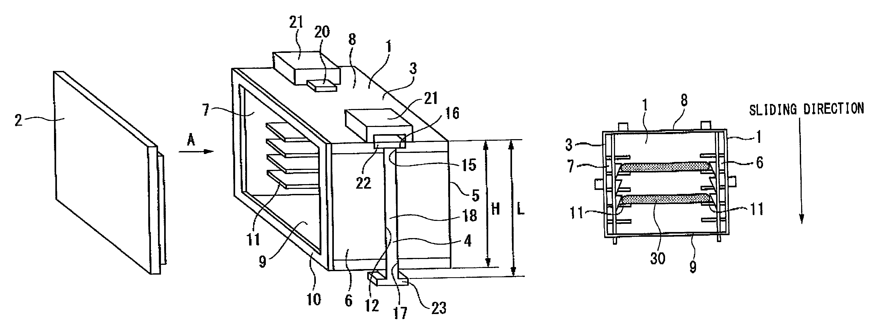
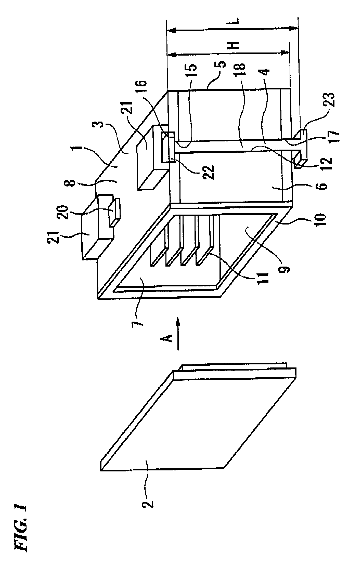
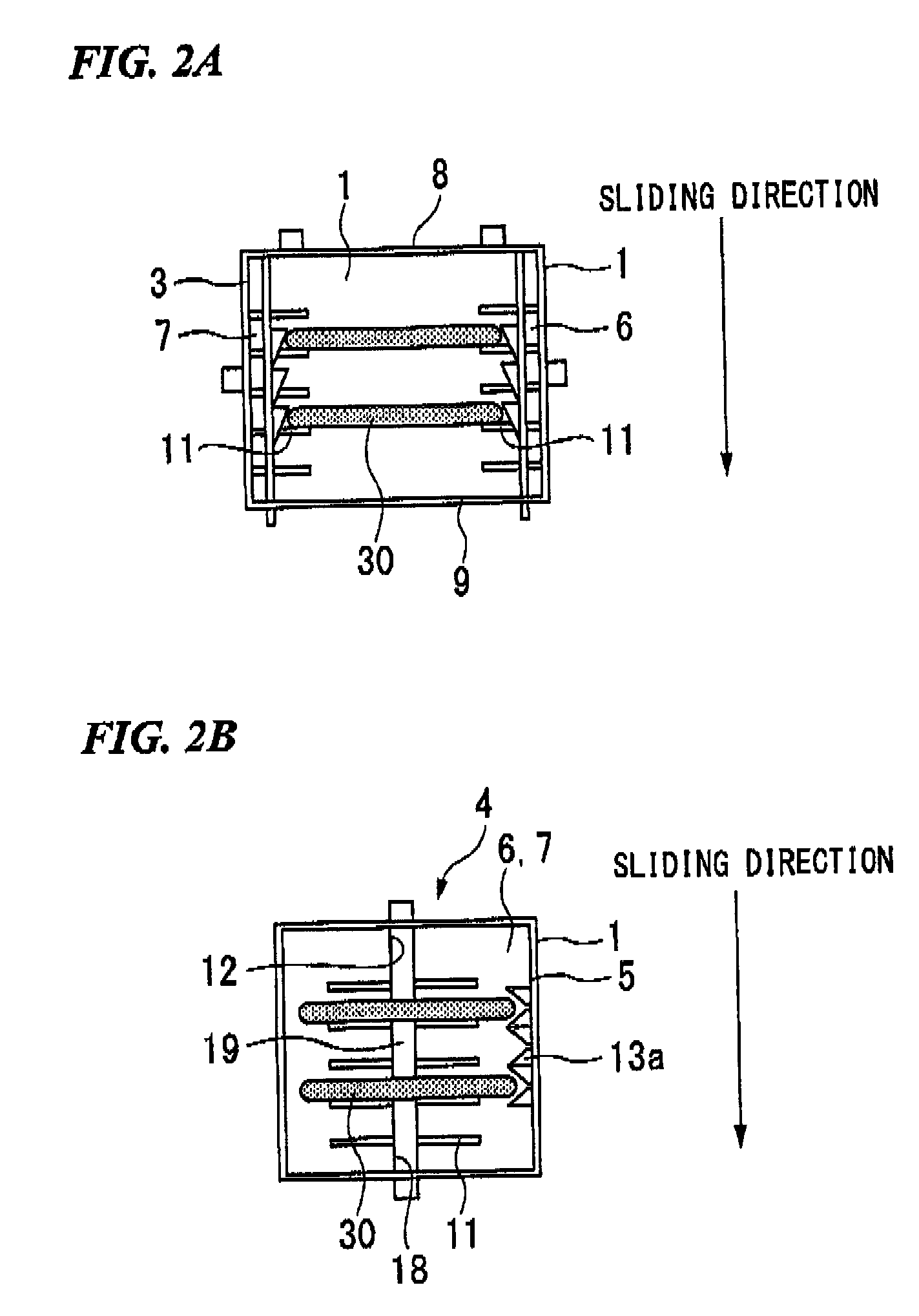
[0053]Hereinbelow, a substrate housing container of the present invention shall be described in detail with reference to drawings. FIG. 1 is a perspective view showing an embodiment of a substrate housing container of the present invention. FIG. 2 is a schematic view showing a slide portion being located in a substrate securing position in the substrate housing container of FIG. 1. FIG. 3 is a schematic view showing a state in which a slide portion is located in a substrate securing releasing position in the substrate housing container of FIG. 1. FIG. 4 is a schematic view showing a lid body provided in the substrate housing container of FIG. 1. FIG. 5 is a schematic view showing a slide portion provided in the substrate housing container of FIG. 1. FIG. 6 is an exploded perspective view showing an upper side of a substrate securing mechanism provided in the substrate housing container of FIG. 1. FIG. 7 is an exploded perspective view showing a lower side of a substrate securing mec...


PUM


Abstract

The present invention includes a ceiling portion 8, bottom portion 9, a substrate housing portion 3 formed by a side walls 5 to 7, a plurality of wafer slots 11 arrayed in parallel on the inner surface of the side walls 6 and 7, a slit portion 12 formed in an extended manner along the array direction of the wafer slots 11 on each of a second side wall 6 and a third side wall 7, a slide portion 18 movably arrayed along each of the slit portions 12, a plurality of substrate securing pieces arrayed with substantially the same intervals with the intervals of the wafer slots 11 on the inner surface of the slide portion 18, in which, with the slide portion being in a substrate securing position, the substrate housing pieces press and secure the substrate on the wafer slot 11, and in a substrate securing releasing position, the substrate housing pieces move separately from a circumferential portion of the substrate and releases a securing state of the substrate. In accordance with the present invention, it is possible to provide a substrate housing container which is able to hold the wafer in a predetermined position even in a case in which the substrate housing container is moved in which a lid body is released.

Description

BACKGROUND OF THE INVENTION[0001]1. Field of the Invention[0002]The present invention relates to a substrate housing container that is used for housing, storing, and transporting or the like of a semiconductor wafer, a glass wafer, or the like.[0003]Priority is claimed on Japanese Patent Application No. 2007-169248, filed on Jun. 27, 2007, the content of which is incorporated herein by reference.[0004]2. Description of the Related Art[0005]Generally, a semiconductor wafer, a glass wafer, or the like is housed or transported in a state where a plurality thereof is housed in a substrate housing container. (Please refer Patent Documents 1 to 3.) In the substrate housing container for housing wafers, it is necessary to support the plurality of wafers which are housed with predetermined intervals so that the wafers do not touch with each other. For this reason, a wafer slot, for supporting the plurality of wafers with the predetermined intervals, is provided, and a substrate securing jig...

Claims


Application Information

Patent Timeline
Patent Type & Authority Patents(United States)
IPC IPC(8): H05K7/18H05K7/14
CPCH01L21/67383
Inventor HOSOKAWA, KOHEI
Owner PS4 LUXCO SARL
Learn More