Motion compensation image coding device and coding method

a motion compensation and image coding technology, applied in the field of motion compensation image coding device and coding method, can solve the problems of reducing coding efficiency and difficulty in real-time coding of large-size frame image data, and achieve the reduction of the amount of data to be interpolated by performing arithmetic operations, the number of blocks to be searched, and the accuracy of 12 or 14 pixels

Active Publication Date: 2011-01-25
RENESAS ELECTRONICS CORP
View PDF8 Cites 12 Cited by
  • Summary
  • Abstract
  • Description
  • Claims
  • Application Information

AI Technical Summary

Benefits of technology

[0009]The technology of varying pixel precision, with which a motion vector is searched, depending on the shape or size of a block may degrade coding efficiency. Moreover, decimal pixel precision may be associated on a fixed basis with a shape of a block that is coded inefficiently.
[0010]The present invention can be applied to a coding method of searching macroblocks and a plurality of kinds of sub-blocks for a motion vector with integer precision or decimal pixel precision, and then code image data with motion data compensated. The present invention provides a technology helpful in greatly reducing the number of arithmetic operations to be performed in order to search a motion vector while substantially ensuring high image quality. The technology in accordance with the present invention is adapted to a motion compensation image coding device and a program that gives instructions to a computer so as to code image data with motion data compensated.
[0012]According to the present invention, when motion data contained in each of macroblocks and sub-blocks is compensated or predicted with ½ or ¼ pixel precision in the same manner as it is according to the motion picture coding methods stipulated by the MPEG-4 and H.264 / AVC standards, the number of blocks to be searched for a motion vector with ½ or ¼ pixel precision is greatly decreased. Consequently, an amount of data to be interpolated by performing arithmetic operations can be markedly reduced. This leads to fast coding.

Problems solved by technology

When numerous kinds of blocks including macroblocks and sub-blocks are employed as stipulated by the H.264 / AVC standard, a problem arises.
In particular, there is difficulty in coding large-size frame image data in real time.
The technology of varying pixel precision, with which a motion vector is searched, depending on the shape or size of a block may degrade coding efficiency.
Moreover, decimal pixel precision may be associated on a fixed basis with a shape of a block that is coded inefficiently.

Method used


Image

  • Motion compensation image coding device and coding method
  • Motion compensation image coding device and coding method
  • Motion compensation image coding device and coding method

Examples


first embodiment

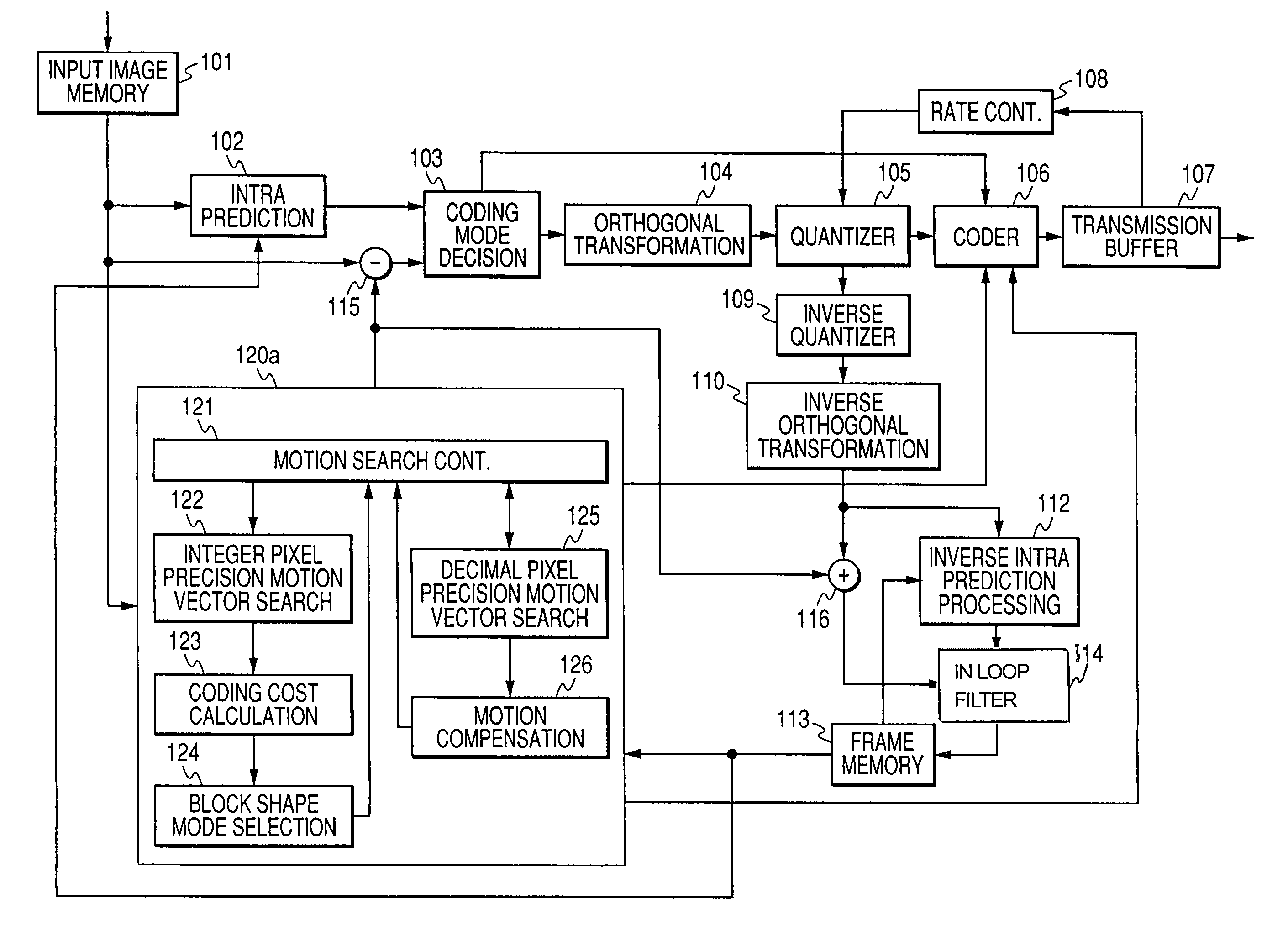
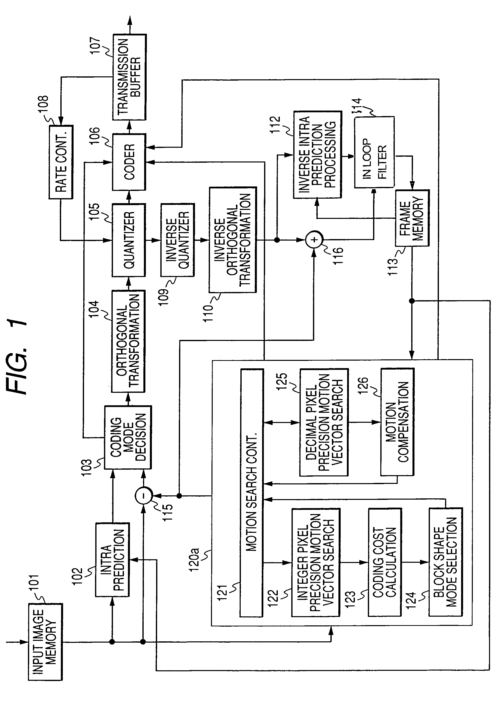
[0023]FIG. 1 is a block diagram showing the configuration of an embodiment of a motion compensation image coding device in accordance with the present invention. As illustrated, the motion compensation image coding device includes an input image memory 101 in which image data is stored, an intra prediction part 102, a coding mode decision part 103, an orthogonal transformation part 104, a quantizer 105, an inverse quantizer 109, an inverse orthogonal transformation part 110, an inverse intra processing part 112, a frame memory 113, an in-loop filter 114, a motion detection / compensation unit 120a, coder 106, a transmission buffer 107, and a rate controller 108.

[0024]All of the above components except the motion detection / compensation unit 120a are substantially identical to those of a conventionally known image data coding device. Namely, data of a raw image frame to be coded is buffered in the input image memory 101. The buffered image frame data is read in units of a macroblock hav...

second embodiment

[0041]FIG. 5 is a block diagram showing the configuration of the second embodiment of a motion compensation image coding device in accordance with the present invention that includes a signal processing unit such as a CPU. The same reference numerals as those written in FIG. 1 are assigned to functional blocks identical to those included in the first embodiment shown in FIG. 1, and an iterative description will be omitted. Data transmission and control illustrated in FIG. 1 are achieved by a control unit 502. Moreover, data is read from the input image memory 101 or frame memory 113 by a DMA reader 509 and transferred to a motion detection / compensation unit 120a.

[0042]The motion detection / compensation unit 120a includes a motion search controller 121, an integer pixel precision motion search part 122, a decimal pixel precision motion search part 125, a motion compensation part 126, and a motion search memory 503. Moreover, the intra prediction part 102 that selects an intra mode, t...

third embodiment

[0043]FIG. 6 is a block diagram showing an example of the configuration of another embodiment of a motion compensation image coding device in accordance with the present invention. The third embodiment is such that before a motion vector detectable with decimal pixel precision is searched, whether a shape mode should be selected is determined. In general, when pixel precision is raised, residuals derived from motion compensation prediction get smaller. Consequently, the number of produced code bits is decreased. Eventually, precision efficiency improves. On the other hand, if pixel precision is raised, the number of pixels to be filtered increases and an arithmetical load increases.

[0044]The same reference numerals as those shown in FIG. 1 are assigned to functional blocks substantially identical to those of the motion compensation image coding device in accordance with the first embodiment shown in FIG. 1, and an iterative description will be omitted. A difference from the motion c...


PUM


Abstract

The present invention provides a technology that is implemented in a motion compensation image coding device or a coding method and intended to code motion picture data in real time by performing a decreased number of arithmetic operations so as to determine a motion vector. In motion compensation image coding, macroblocks and sub-blocks into which each of the macroblocks is divided are searched for a motion vector with integer pixel precision. Based on the results of the search, a shape of a block that should be searched for a motion vector with decimal pixel precision is determined as a shape mode. The block of the shape mode is searched for a motion vector with decimal pixel precision, whereby a motion vector needed to produce predictive image data is determined.

Description

BACKGROUND OF THE INVENTION[0001](1) Field of the Invention[0002]The present invention relates to a motion compensation image coding device and coding method. More particularly, the present invention is concerned with a coding technology for compressing motion picture data, that is, for compensating or predicting a motion in units of each of blocks into which frame data contained in motion picture data is divided, and coding a residual signal, which represents a difference between produced predictive image data and the frame data of the motion picture data, and motion data (that is, a motion vector). The present invention is concerned especially with a technology for searching a motion vector that is included in the compressive coding technology.[0003](2) Description of the Related Art[0004]In recent years, motion picture coding devices that adopt interpolative coding, motion compensation prediction, orthogonal transformation, quantization, and variable length coding and that are re...

Claims


Application Information

Patent Timeline
Patent Type & Authority Patents(United States)
IPC IPC(8): H04N7/12H04N19/105H04N19/109H04N19/50H04N19/119H04N19/127H04N19/136H04N19/137H04N19/156H04N19/176H04N19/196H04N19/503H04N19/51H04N19/523H04N19/53H04N19/59H04N19/61H04N19/625H04N19/86H04N19/91
CPCH04N5/145H04N19/57H04N19/523
Inventor SAITO, SHOHEIHASE, MASARUIZUHARA, FUMITAKAMOCHIZUKI, SEIJI
Owner RENESAS ELECTRONICS CORP
Why Eureka
Try Eureka