Apparatus and method for composite material trim-on-the-fly

a composite material and aircraft technology, applied in the direction of process and machine control, mechanical control devices, instruments, etc., can solve the problems of complex and expensive apparatus, inability to cut quickly, and inability to meet the requirements of aircraft, etc., to achieve rapid cutting and increase production rate

Inactive Publication Date: 2011-02-01
THE BOEING CO
View PDF18 Cites 42 Cited by
  • Summary
  • Abstract
  • Description
  • Claims
  • Application Information

AI Technical Summary

Benefits of technology

According to other embodiments the present invention is a novel system of dispensing, feeding, trimming and lay-up of composite material to form a multiple layer composite part where the composite material passes through a trimming system with at least one cutting device capable of being moved in multiple axes such that it can trim the periphery of the composite material to the desired shape without the material changing speed.
In many embodiments of this invention the technical advance lies in cutting the material while it is in motion and in the form of a single layer. This allows very rapid cutting and an increase in production rate over many of the earlier methods used.

Problems solved by technology

However, for some applications the existing apparatus has certain drawbacks.
Automated Tape Layer (ATL) apparatus places single layers of uncured composite pre-impregnated material on flat or contoured surfaces, but the apparatus is extremely complex and very expensive.
The tape dispensed is unidirectional, so when making long, narrow parts where an angled ply or cross ply is needed, the tape laying head must traverse the part once for each width of tape, which makes the process extremely slow.
While this method works, it is relatively slow, subject to human error, and not well suited to the production rates found in the manufacture of commercial aircraft.

Method used


Image

  • Apparatus and method for composite material trim-on-the-fly
  • Apparatus and method for composite material trim-on-the-fly
  • Apparatus and method for composite material trim-on-the-fly

Examples


Embodiment Construction

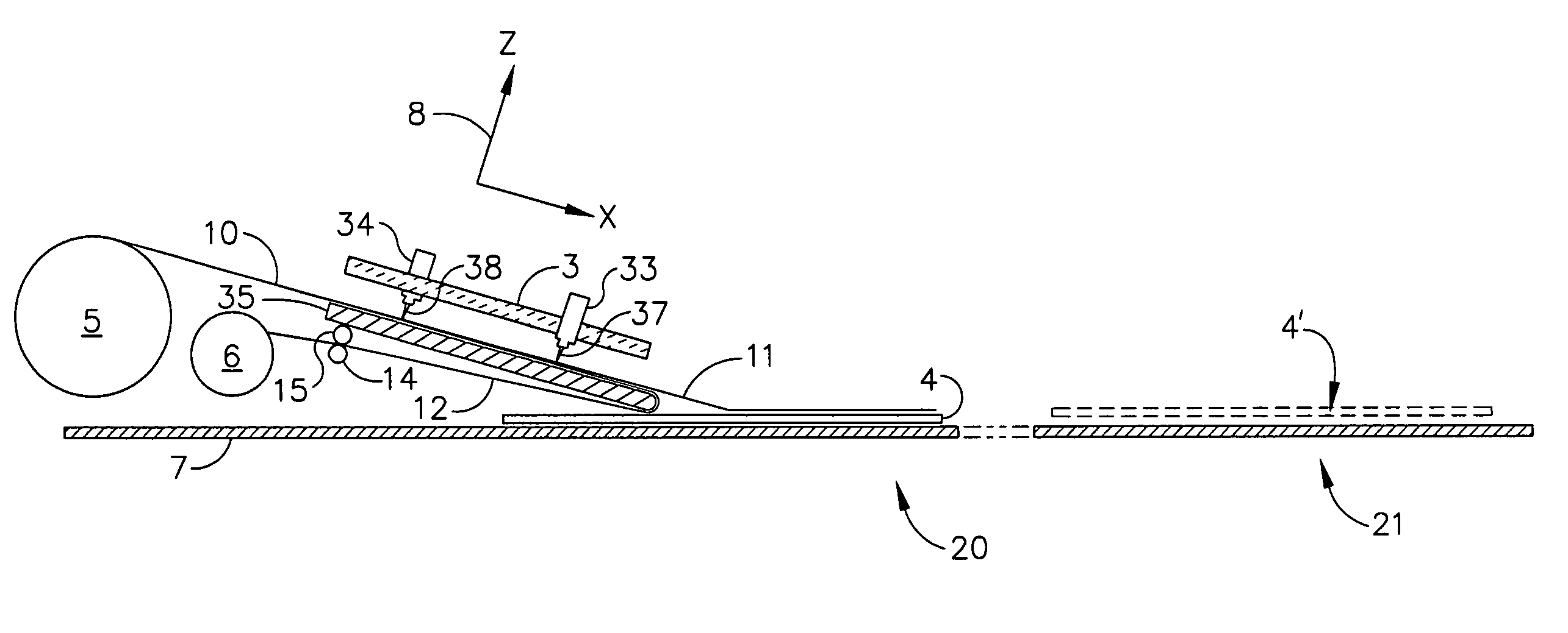
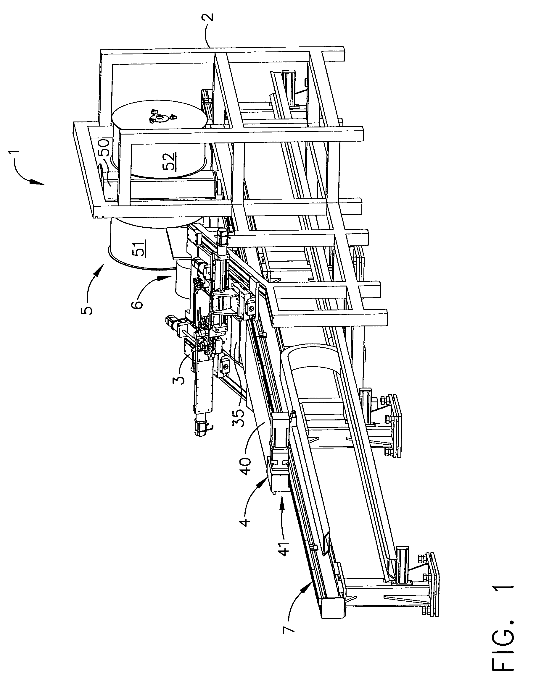
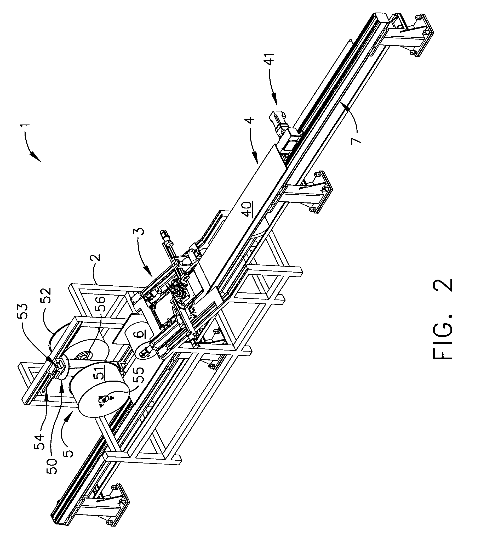
Referring particularly to FIGS. 1 and 2 of the drawings, a preferred embodiment of a composite trim and lay-up system is shown at 1. The composite trim and lay-up system 1 may include a frame 2, a material supply system 5, a feed and trim system 3, a lay-up table 4, and a backing material take-up reel 6.

In a number of embodiments, the material supply system 5 may include a supply system pivot 50 with two axles 55 and 56 mounted thereon for removably placing composite material supply reels 51 and 52. The supply system pivot 50 may advantageously have a supply system pivot latch 53 and a supply system pivot lever 54. The system may in some embodiments be configured with a single supply reel, or may have more than two supply reels by arranging them in a carousel or any of a number of other known mechanisms to bring them into the feed position as desired.

As best shown in FIG. 4, a layer of composite material 11 may be attached to a backing material 12, which may be a paper or a plastic ...


PUM

PropertyMeasurementUnit
dimensionsaaaaaaaaaa
speedaaaaaaaaaa
widthaaaaaaaaaa

Abstract

Disclosed is a method and apparatus for manufacturing multiple layer composite structures and structures containing components made of multiple layer composite structures, comprising dispensing layers of composite material, trimming each layer to its final shape as it is being dispensed, and positioning it properly with respect to prior layers in the part lay-up.

Description

BACKGROUND OF THE INVENTION1. Field of the InventionThe present invention relates to composite structures and their methods of manufacture, more particularly to structures used in composite aircraft construction.2. Description of Related ArtApparatus for the manufacture of structures from layers of composite material are well known. However, for some applications the existing apparatus has certain drawbacks.Automated Tape Layer (ATL) apparatus places single layers of uncured composite pre-impregnated material on flat or contoured surfaces, but the apparatus is extremely complex and very expensive. The tape dispensed is unidirectional, so when making long, narrow parts where an angled ply or cross ply is needed, the tape laying head must traverse the part once for each width of tape, which makes the process extremely slow.Another method of manufacturing composite parts is by use of Automated Fiber Placement (AFP) equipment. This is similar in nature to the ATL process discussed above...

Claims


Application Information

Patent Timeline
Patent Type & Authority Patents(United States)
IPC IPC(8): B29C65/56B32B37/26B32B37/18B32B37/14B32B37/02B29C65/72B32B38/10B26D5/02B32B37/10B29C65/78B26D3/08
CPCB29C70/386B29C70/545Y10T156/1322B29L2031/3082B29L2031/3085Y10T156/1064Y10T156/125Y10T156/1348Y10T156/1098Y10T156/13Y10T156/108Y10T156/17Y10T156/1075Y10T156/1082Y10T156/1054Y10T156/12
Inventor MCCOWIN, PETER D.JONES, DARRELL D.BANKS, DAVID P.ZENKNER, GRANT C.
Owner THE BOEING CO
Why Eureka
Try Eureka