Pressure wave generator and production method therefor

a technology of pressure wave generator and production method, which is applied in the direction of mechanical vibration separation, instruments, semiconductor electrostatic transducers, etc., can solve the problems of deteriorating the insulating property of the porous silicon layer, narrow frequency band, and easy external vibration or fluctuation, so as to prevent a reduction in output

Inactive Publication Date: 2011-02-01
MATSUSHITA ELECTRIC WORKS LTD
View PDF7 Cites 17 Cited by
  • Summary
  • Abstract
  • Description
  • Claims
  • Application Information

AI Technical Summary

Benefits of technology

[0009]Therefore, in consideration of the above problems, a primary concern of the present invention is to provide a pressure wave generator capable of preventing a reduction in output caused by a change over time of a heat insulating layer.
[0010]That is, the pressure wave generator of the present invention comprises a substrate, a heat generating layer, and a heat insulating layer formed between the substrate and the heat generating layer. The pressure wave generator is configured to generate a pressure wave in a surrounding medium by a change in temperature of the heat generating layer, which is caused upon energization of the heat generating layer. The heat insulating layer comprises a porous layer and a barrier layer formed between the porous layer and the heat generating layer to prevent diffusion of a component of the medium into the porous layer.
[0011]According to the present invention, since the heat insulating layer has the barrier layer formed on the porous layer at a side facing the heat generating layer, it is possible to prevent deterioration of thermal properties, which is caused when reactive substances such as oxygen and moisture in the surrounding medium (e.g., air) and impurities are diffused into the porous layer, adsorbed or adhered to the porous layer, or reacted with the porous layer. As a result, a reduction in output caused by a change over time of the heat insulating layer can be suppressed.

Problems solved by technology

However, since the above-mentioned ultrasonic wave generator has a characteristic resonance frequency, there are problems that the frequency band becomes narrow, and it is susceptible to external vibrations or fluctuations of outside air pressure.
That is, when oxidation of the porous silicon layer proceeds by the influence of oxygen and moisture in the air, the heat insulating property of the porous silicon layer deteriorates, so that a reduction in the aforementioned efficiency happens.
As a result, there is a case that an object can not be detected.
In addition, when the pressure wave generator is used as a speaker, there is a problem that the sound pressure reduces.
As a result, the pressure wave generator may have a breakdown due to burn out of the heat generating layer.

Method used


Image

  • Pressure wave generator and production method therefor
  • Pressure wave generator and production method therefor
  • Pressure wave generator and production method therefor

Examples


Embodiment Construction

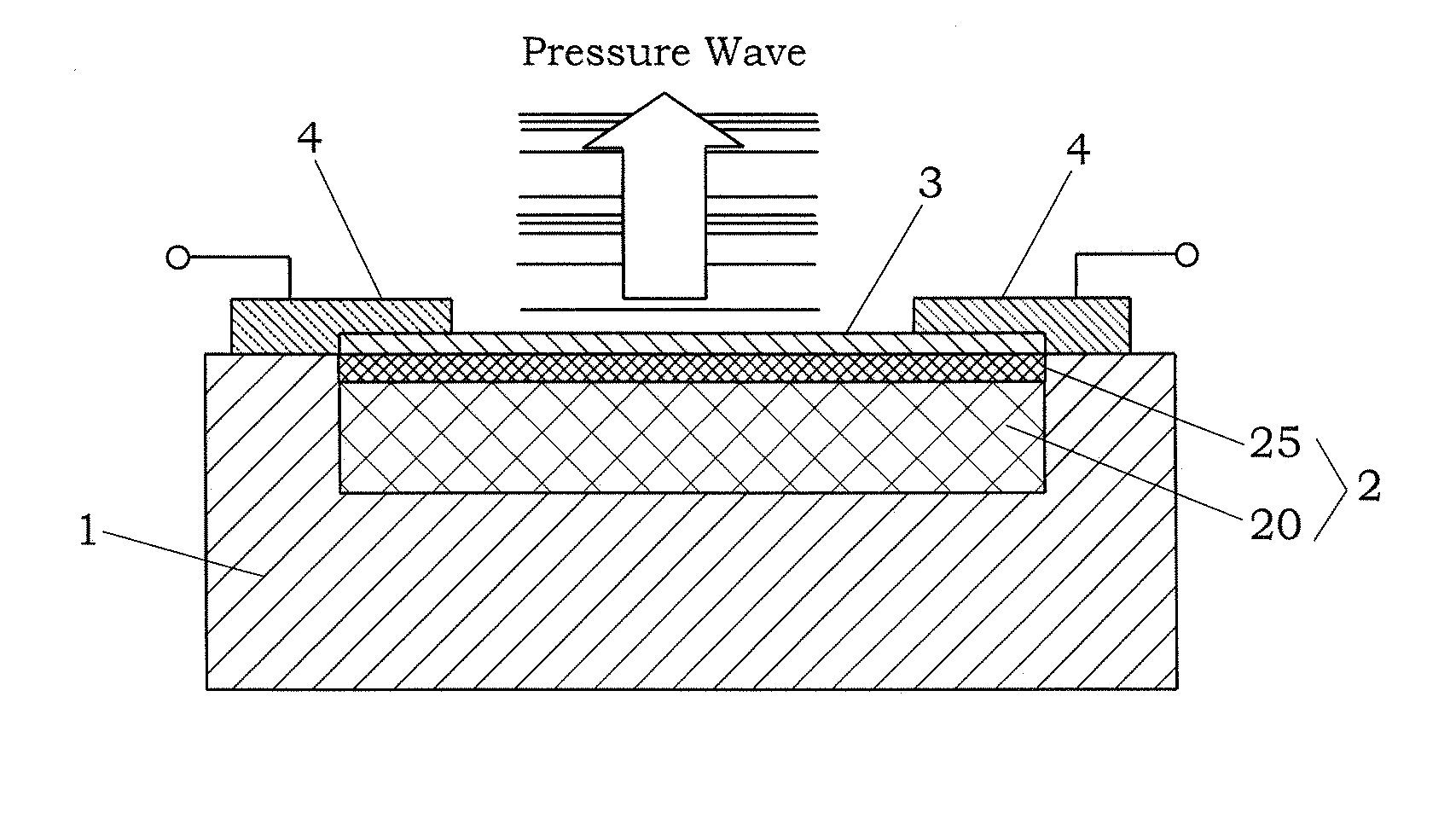
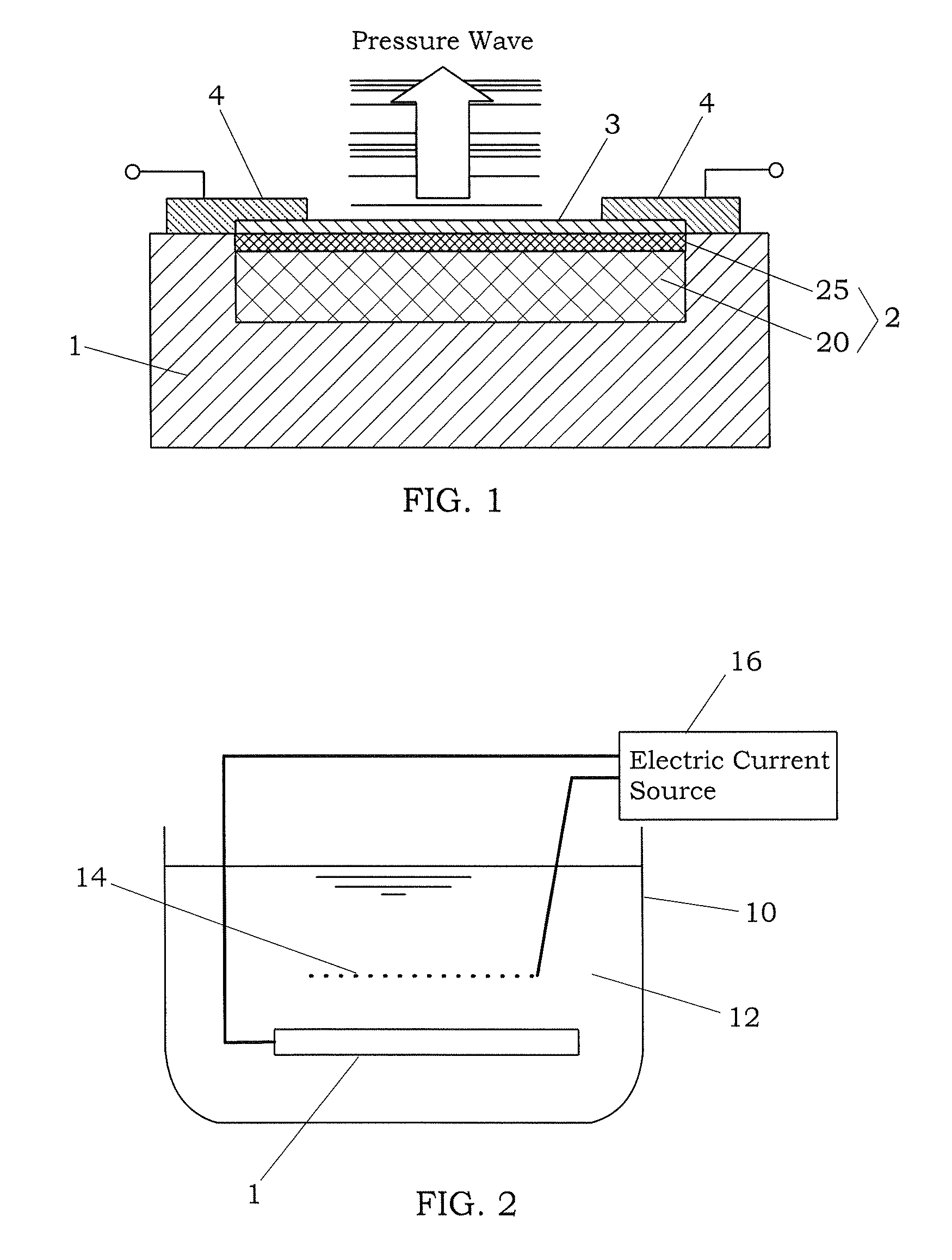
[0038]The pressure wave generator and the production method of the present invention are explained below in detail according to preferred embodiments, referring to the attached drawings.

[0039]As shown in FIG. 1, the pressure wave generator of the present embodiment has a substrate 1 made of single crystal silicon, a heat generating layer 3 formed by a metal thin film, a heat insulating layer 2 formed between the substrate 1 and the heat generating layer 3, and a pair of pads 4 formed on both end portions of the heat generating layer 3. A change in temperature of the heat generating layer 3 caused upon energization of the heat generating layer 3 through the pair of pads 4 gives a thermal shock to the air of the surrounding medium to generate a pressure wave. In the present embodiment, since a driving voltage waveform or a driving current waveform is applied to the heat generating layer 3, the temperature change occurs in the heat generating portion 3 in response to this driving input...


PUM


Abstract

A pressure wave generator is provided, which has excellent output stability over time. This pressure wave generator comprises a substrate, a heat generating layer, and a heat insulating layer formed between the substrate and the heat generating layer. A pressure wave is generated in a surrounding medium (air) by a change in temperature of the heat generating layer, which is caused upon energization of the heat generating layer. The heat insulating layer comprises a porous layer and a barrier layer formed between the porous layer and the heat generating layer to prevent diffusion of reactive substances such as oxygen and moisture in the air and impurities into the porous layer. By the formation of the barrier layer, it is possible to prevent a reduction in output of the pressure wave generator caused by a change over time of the porous layer.

Description

TECHNICAL FIELD[0001]The present invention relates to a pressure wave generator, which is preferable in applications such as speaker and ultrasonic sensor, and a production method for the same.BACKGROUND ART[0002]In the past, an ultrasonic wave generator using mechanical vibrations due to the piezoelectric effect has been widely known. As this kind of ultrasonic wave generator, for example, there is a structure where electrodes are formed on both surfaces of a crystal of a piezoelectric material such as barium titanate. The mechanical vibrations obtained by applying an electric energy between the electrodes generate the ultrasonic wave in a surrounding medium (e.g., air). However, since the above-mentioned ultrasonic wave generator has a characteristic resonance frequency, there are problems that the frequency band becomes narrow, and it is susceptible to external vibrations or fluctuations of outside air pressure.[0003]On the other hand, in recent years, a pressure wave generator c...

Claims


Application Information

Patent Timeline
Patent Type & Authority Patents(United States)
IPC IPC(8): H04R23/00B06B1/00
CPCB06B1/02H04R19/005H04R23/002H04R31/00H04R17/00
Inventor WATABE, YOSHIFUMIHONDA, YOSHIAKI
Owner MATSUSHITA ELECTRIC WORKS LTD
Why Eureka
Try Eureka