Image forming apparatus and image density control method

a technology of image density and forming apparatus, which is applied in the direction of electrographic process apparatus, instruments, optics, etc., can solve the problems of inability to obtain constant image density, inability to fix the charge of toner that contributes to development, and inability to fix the development ability, etc., to achieve the effect of suppressing the amount of toner consumed and constant image density

Inactive Publication Date: 2011-02-01
RICOH KK
View PDF24 Cites 11 Cited by
  • Summary
  • Abstract
  • Description
  • Claims
  • Application Information

AI Technical Summary

Benefits of technology

[0014]The present invention has been designed in consideration of the background described above, and an object thereof is to provide an image forming apparatus and an image density control method which are capable of suppressing the amount of toner consumed for a purpose other than image formation and responding to variation in the development ability of a development device due to environmental variation and the like such that a constant image density is obtained.

Problems solved by technology

Moreover, although development conditions such as the development potential can be fixed comparatively easily, it is difficult to fix the charge of the toner that contributes to development.
Hence, even if the development conditions are fixed and toner concentration control is performed to fix the toner concentration, the development ability cannot be fixed, and therefore a constant image density cannot be obtained.
Accordingly, the amount of toner that remains in the development device for a comparatively long time is large.
The toner that remains in the development device for a comparatively long time is agitated for a long time, and therefore the toner in the development device is more likely to be excessively charged.
Hence, the development ability is comparatively low.
In contrast, when an image with a high image area ratio is output, the amount of new replenishment toner that is not sufficiently charged is large, and therefore the proportion of toner that is not charged to the desired charge within the toner that contributes to development is large.
For example, when toner having an adhered additive is used and a development device in which the toner is subjected to a high level of stress is employed, the additive may become buried in or separate from the toner surface of the toner that has existed in the development device for a comparatively long time as a result of long-term agitation.
When a large amount of such toner exists, the fluidity of the developer deteriorates and the charging ability of the toner decreases, and as a result, the toner that contributes to development cannot be charged to the desired charge.
In contrast, when an image with a high image area ratio is output, the replenishment toner amount is large, and therefore the amount of toner that has existed in the development device for a comparatively long time is small.
Therefore, the fluidity of the developer is sufficiently favorable, and the amount of toner having a sufficient charging ability is large.
Accordingly, the toner that contributes to development can be charged to the desired charge, and therefore the development ability is comparatively low.
Hence, even when the development conditions are fixed and toner concentration control is performed to fix the toner concentration, the development ability cannot be fixed, and therefore a constant image density cannot be obtained.
However, in the image forming apparatus described in these publications, the reference toner pattern must be formed every time the toner concentration control reference value is corrected, leading to an increase in the amount of toner consumed for a purpose other than image formation.
However, this image forming apparatus is incapable of responding to variation in the development ability of the development device due to factors other than the toner replacement amount in the development device over a predetermined time period, for example environmental variation, the standing time, and so on.
Therefore, the image density cannot be controlled appropriately by the inventions proposed in the related art.

Method used


Image

  • Image forming apparatus and image density control method
  • Image forming apparatus and image density control method
  • Image forming apparatus and image density control method

Examples


Embodiment Construction

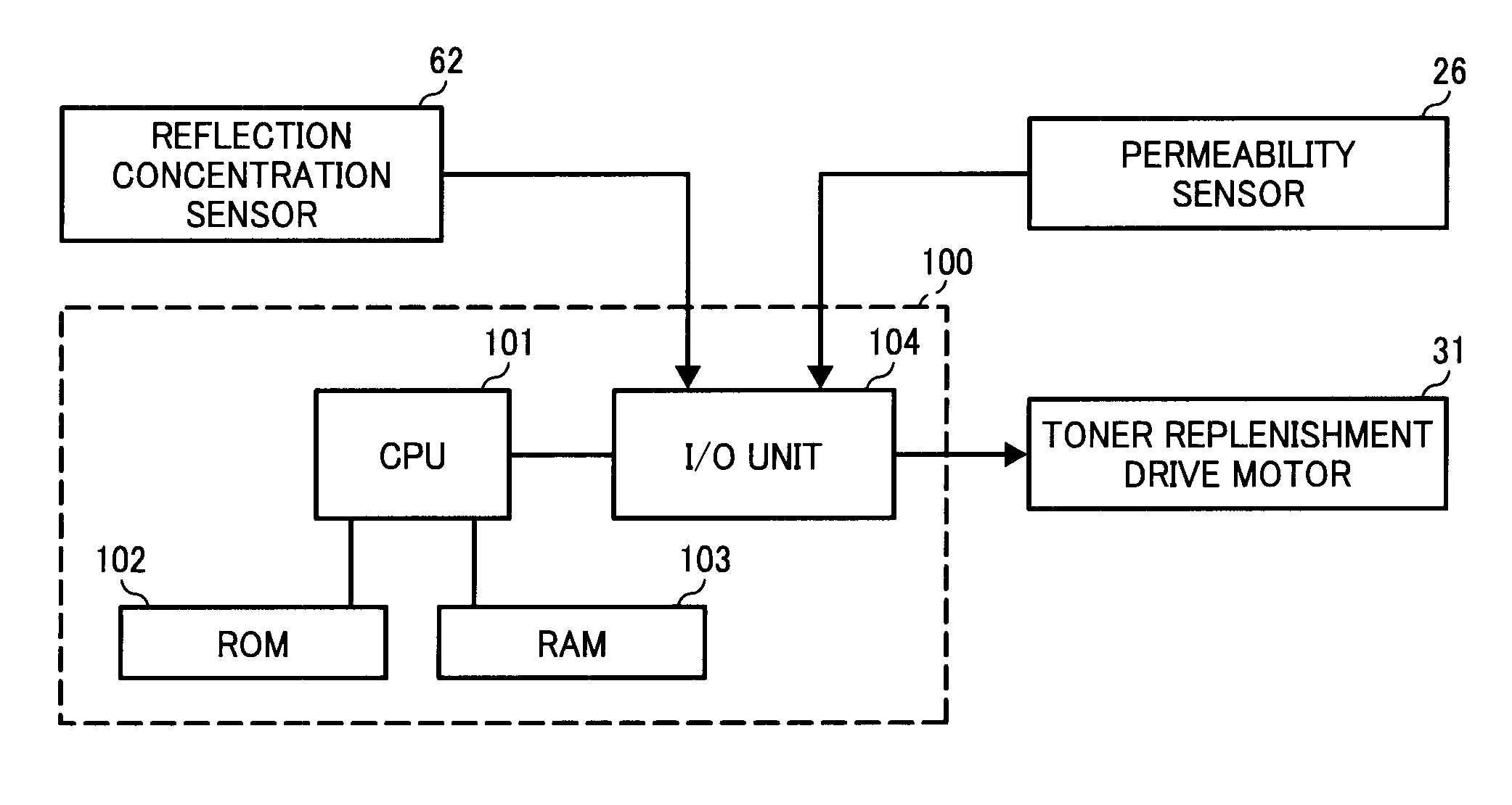
[0030]First, an outline of the present invention will be described.

[0031]As described above, a constant image density cannot be obtained due to variation in the development ability resulting from differences in the amount of new replenishment toner or old toner in a development device. Hence, in the present invention, information for learning a toner replacement amount in the development device over a predetermined time period is detected. From this information, it is possible to learn the amount of toner in the development device that is consumed within the predetermined time period and the required amount of new replenishment toner. In other words, it is possible to learn the ratio of new toner or the ratio of old toner in the development device. Thus, the development ability can be learned, and therefore, on the basis of the information detection result, a toner concentration control reference value can be corrected by first toner concentration control reference value modifying m...


PUM


Abstract

In an image forming apparatus and an image density control method that are capable of suppressing the amount of toner consumed for a purpose other than image formation and responding to variation in the development ability of a development device due to environmental variation and the like such that a constant image density is obtained, the image density is maintained at a substantially fixed level by first target output value correcting means in accordance with a toner replacement amount and without consuming toner, and adjustment of the image density accompanying variation in the development ability due to environmental variation and the like is dealt with by second target output value correcting means in accordance with a toner pattern detection result. Hence, the frequency with which the toner pattern is detected in order to maintain the image density at a fixed level can be reduced in comparison with a case in which the image density is maintained at a fixed level on the basis of the toner pattern detection result alone, and as a result, the toner consumption amount can be suppressed.

Description

BACKGROUND OF THE INVENTION[0001]1. Field of the Invention[0002]The present invention relates to an image forming apparatus such as a copier, printer, or facsimile device for forming an image using a two-component developer constituted by a toner and a magnetic carrier, and an image density control method.[0003]2. Description of the Related Art[0004]A two-component development system in which a two-component developer (to be referred to hereafter simply as “developer”) constituted by a toner and a magnetic carrier is held on a developer carrier, the developer is used to form a magnetic brush by means of a magnetic pole provided in the interior of the developer carrier, and development is performed by sliding the magnetic brush over a latent image formed on a latent image carrier is known widely in the related art. The two-component development system is used widely due to the ease with which color images can be formed thereby. In the two-component development system, background stai...

Claims


Application Information

Patent Timeline
Patent Type & Authority Patents(United States)
IPC IPC(8): G03G15/10G03G15/08
CPCG03G15/1605G03G15/0853G03G15/0849G03G2215/0161
Inventor TAKEUCHI, NOBUTAKAISHIBASHI, HITOSHIFUJIMORI, KOHTATANAKA, KAYOKOHIRAYAMA, YUSHIWATANABE, NAOTO
Owner RICOH KK
Why Eureka
Try Eureka