Roof vent base plate and installation methods

a technology for venting and base plates, applied in ventilation systems, building repairs, heating types, etc., can solve the problems of increasing the likelihood of leakage at the central opening, and achieve the effect of preventing leakage and resultant property damag

Inactive Publication Date: 2011-02-08
WEST G LEONARD
View PDF34 Cites 28 Cited by
  • Summary
  • Abstract
  • Description
  • Claims
  • Application Information

AI Technical Summary

Benefits of technology

[0010]Preferred embodiments include a base plate that can be used in conjunction with a vent cap such as a cover, stack flashing, penetration or the like. The preferred base plate includes a substantially planar attachment portion and an aperture located within the attachment portion. The base plate further includes a collar or curb circumscribing the aperture; wherein the collar preferably defines a cylindrical channel. In further preferred embodiments the cylindrical channel is of a generally uniform diameter and the collar extends perpendicularly from the substantially planar attachment portion. Preferably, the collar extends upwardly when the attachment portion is operatively installed around the roof exhaust source. The preferred base plate substantially prevents any water that enters the vent cap from getting into the roof exhaust source, by diverting water away from the roof exhaust source, thus preventing leaks and resultant property damage.
[0012]The preferred base plate includes an adhesive layer on a bottom surface of the generally planar attachment portion. The adhesive layer may cover a portion, most of or all of the bottom surface. The adhesive layer is preferably configured such that the base plate can be secured to the roof deck or underlayment with the adhesive. Suitable adhesives include, but are not limited to, rubberized asphalt adhesive, modified bitumen adhesives, acrylic or latex sealants or the like. In further preferred embodiments, the adhesive layer has a removable protective sheet such that the adhesive is covered until installation. This is highly preferred as it will make installation fast and easy as no separate tubes of adhesive or caulk will need to be carried or applied by the installer. In addition, this method is much less messy as there is nothing to drip or smudge. The installer can simply peel off the adhesive layer and press the adhesive onto the roof deck or underlayment.

Problems solved by technology

Such construction can lead to an increased likelihood of leakage at the central opening.

Method used


Image

  • Roof vent base plate and installation methods
  • Roof vent base plate and installation methods
  • Roof vent base plate and installation methods

Examples


Embodiment Construction

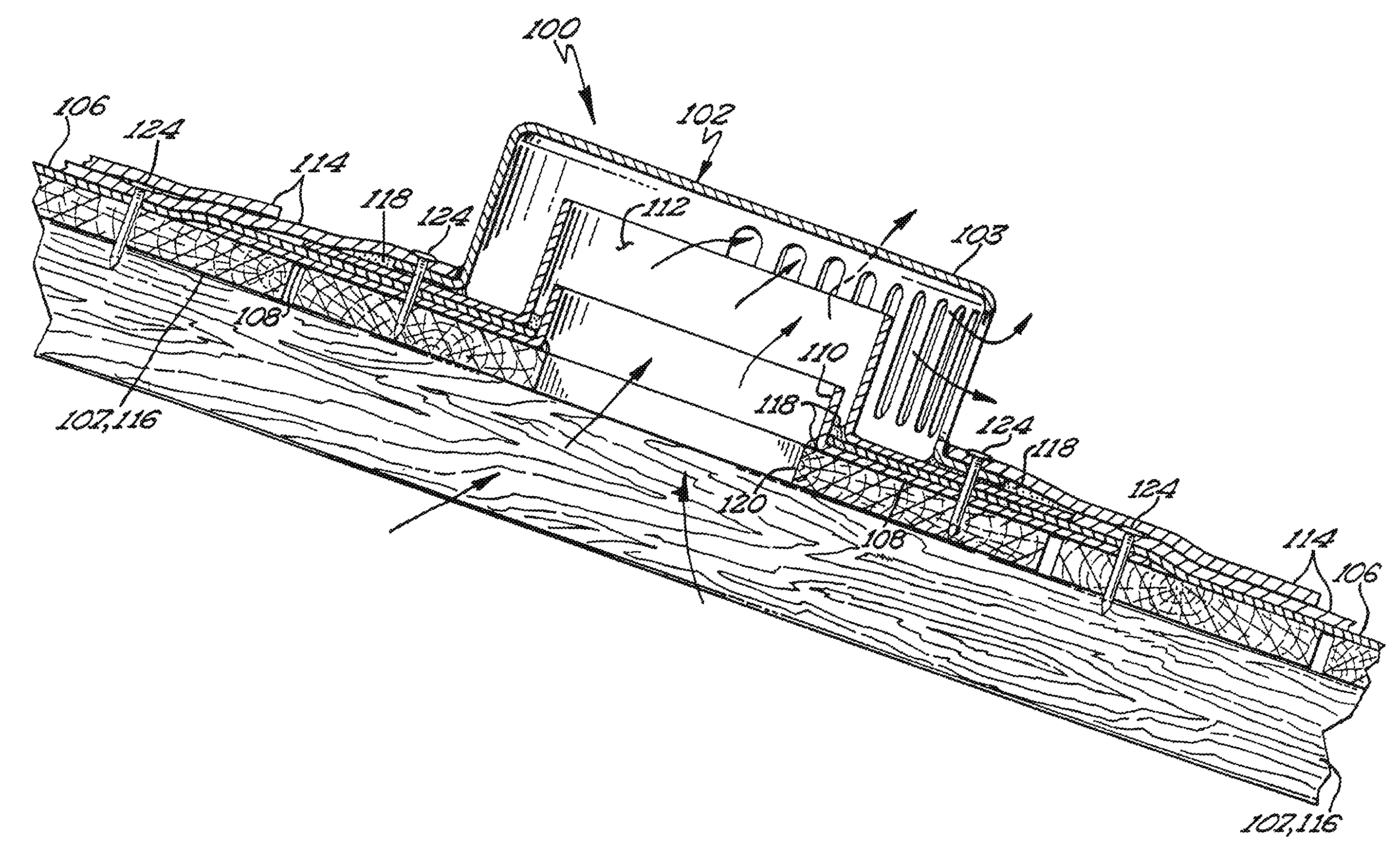
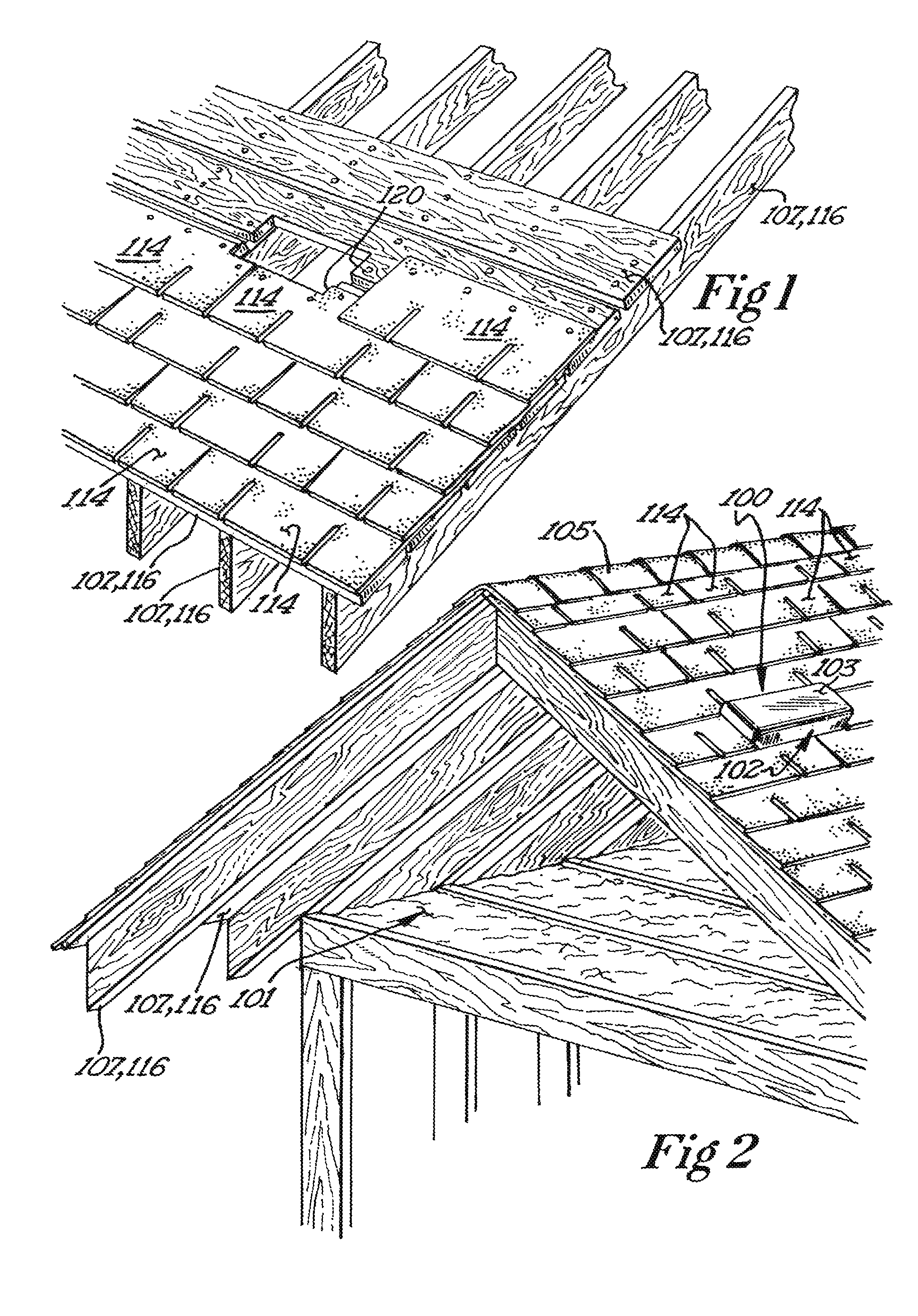
[0023]The amount of water intrusion into our homes and businesses are at almost epidemic levels. Roof leaks have always been at the top of the list for a cause of water intrusion. A good roof system requires quality materials and detailed installation. Most roof leaks occur at the penetrations or vent caps in the roof. These penetrations being attic vents, plumbing vents, vent stacks for furnaces and fireplaces, bathroom vents and the like.

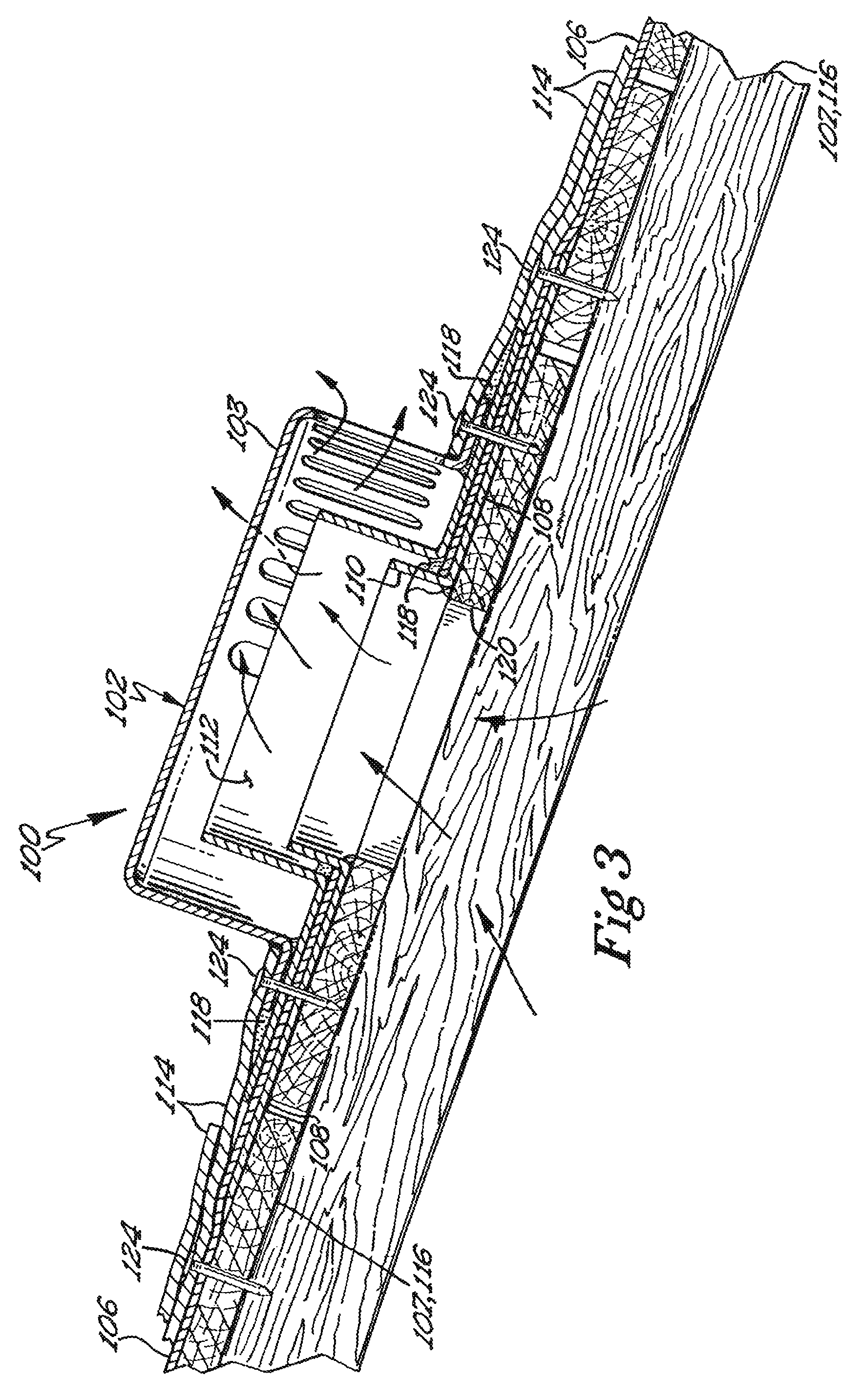
[0024]There are many different methods used when installing a roof-top vent caps. Sealants (e.g. tar, caulking and the like) and mastics (e.g. ice and water shield) are the practiced method used to make vent openings or roof exhaust sources leak-proof. The inventor has found that the use of sealants and mastics can be messy and can actually damage the roof system if not properly used. Moreover, these sealants and mastics can be subject to UV degradation. Expansion and contraction from weather extremes can further damage their effectiveness in prev...


PUM


Abstract

A roof ventilation apparatus for a sloped roof having a cap and base plate is provided. The cap has a top surface and a bottom surface. The bottom surface has a flange that defines an opening to a cavity formed between the top and bottom cap surface. The cavity provides a path for air exchange from a roof opening through an air passage formed between the flange and cap top. The base plate has a collar or curb surrounding an aperture that fits inside the cap bottom cavity. The base plate preferably is shaped such that when installed on the sloped roof the cap entirely covers the base plate. Preferably, the base plate includes a collar and an angled edge configured to channel moisture that seeps within the vent cap.

Description

RELATED APPLICATIONS[0001]The present application is related to and claims priority to U.S. patent application Ser. No. 10 / 918,925, filed Aug. 17, 2004, currently pending, and is titled ROOF VENT AND METHOD OF INSTALLATION, wherein the aforementioned application is incorporated herein by reference.FIELD OF THE INVENTION[0002]The present invention is directed to a base plate that can be used in combination with roof vent caps such as covers, stack flashings, penetrations or the like. More specifically, the present invention is directed to a base plate that directs water away from a roof exhaust source. Even more particularly, the present invention relates to a base plate having an adhesive layer such that the base plate can be easily secured to a roof deck.BACKGROUND OF THE RELATED ART[0003]It is desirable to provide ventilation for the areas beneath building roofs to reduce the accumulation of heat and to reduce the accumulation of moisture in the attic or other spaces immediately b...

Claims


Application Information

Patent Timeline
Patent Type & Authority Patents(United States)
IPC IPC(8): E04C1/00
CPCE04D13/1476E04D13/17F24F7/02
Inventor WEST, G. LEONARD
Owner WEST G LEONARD
Why Eureka
Try Eureka