Directional coupler in coaxial line technology

a technology of directional couplers and coaxial lines, which is applied in the direction of waveguide devices, electrical equipment, and impedence networks, etc., can solve the problems of comparatively high complexity of mechanical and also electrical connection between coaxial lines, disadvantageous mounting in a common housing, and comparatively complex configuration of heat discharge bars, so as to achieve the effect of minimising additional complexity

Inactive Publication Date: 2011-02-08
ROHDE & SCHWARZ GMBH & CO KG
View PDF7 Cites 2 Cited by
  • Summary
  • Abstract
  • Description
  • Claims
  • Application Information

AI Technical Summary

Benefits of technology

[0008]The object therefore underlying the invention is to produce a directional coupler in coaxial line technology in which the mechanical and also electrical connection between the coaxial line and the connections of the directional coupler, in particular the decoupling connections, is produced with minimal additional complexity with respect to the technical appliance.

Problems solved by technology

The comparatively high complexity with respect to a mechanical and also electrical connection between the coaxial line and the two decoupling units and the connections thereof via a common spacing, attachment and mounting in a common housing is disadvantageous in this arrangement.
Also the specific and efficient discharge of heat produced from the directional coupler circuit by means of resistors and heat discharge bars has a comparatively complex configuration.

Method used


Image

  • Directional coupler in coaxial line technology
  • Directional coupler in coaxial line technology
  • Directional coupler in coaxial line technology

Examples


Embodiment Construction

)

[0020]The directional coupler according to the invention in coaxial line technology is described in its embodiment subsequently with reference to FIG. 1 to FIG. 3.

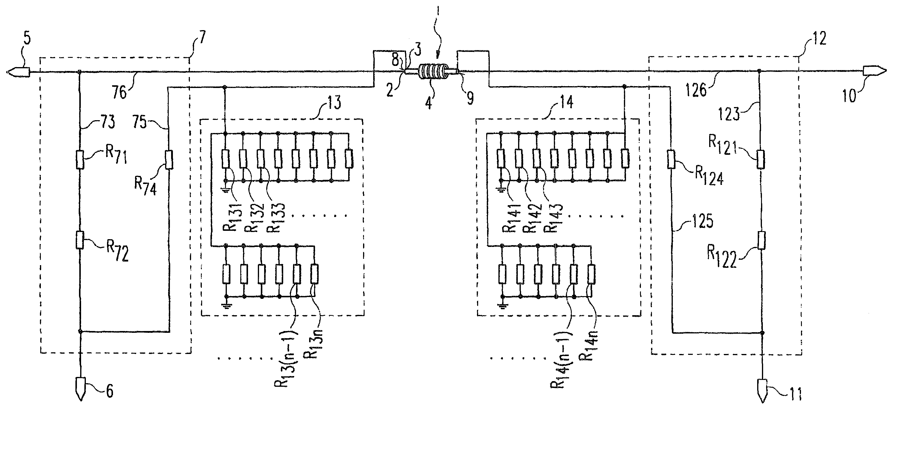
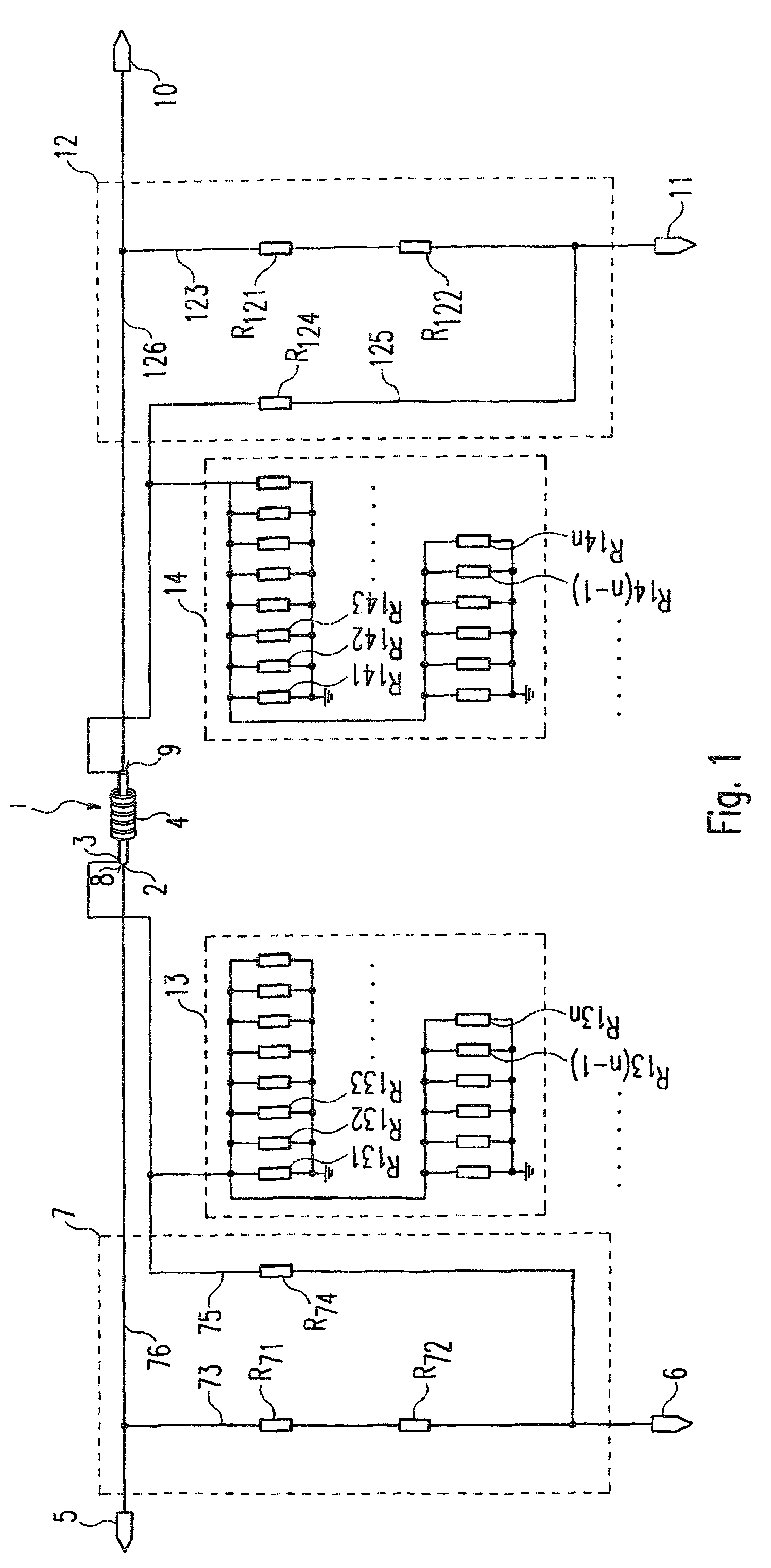
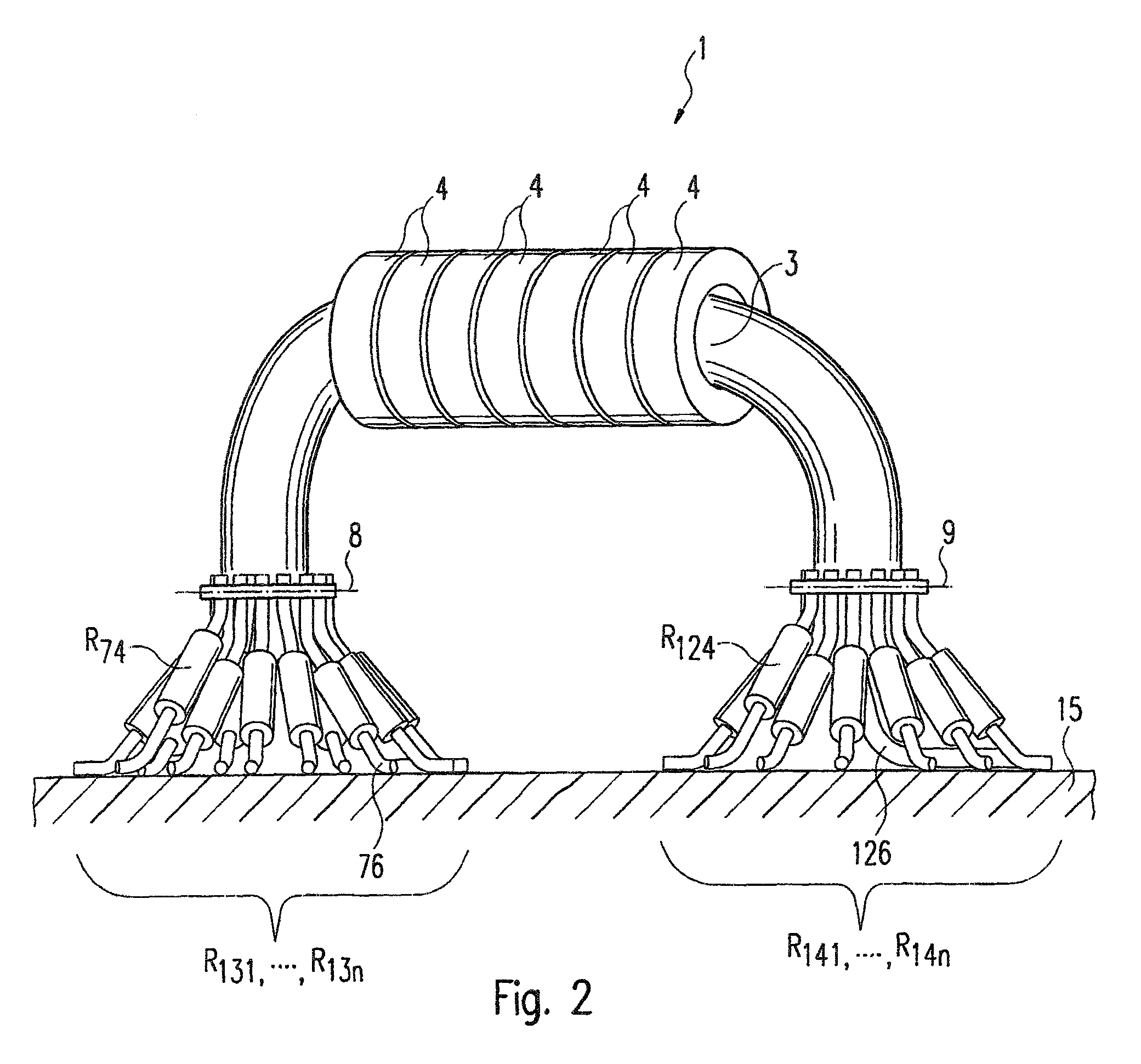
[0021]The directional coupler according to the invention in coaxial line technology comprises according to FIG. 1 essentially a coaxial line 1 which comprises an inner conductor 2 and an outer conductor 3 separated via a dielectric. The coaxial line 1 is surrounded on its outer casing by a plurality of aligned ferrite core rings 4.

[0022]The coaxial line 1 is connected at its first connection face 8 to the first connection 5 and to the first decoupling connection 6 of the directional coupler via a first resistance network 7 and, at its second connection face 9, to the second connection 10 and to the second decoupling connection 11 via a second resistance network 12 which is symmetrical to the first resistance network 7.

[0023]The first resistance network 7 comprises a series connection of a resistor R71 and R72 in the conne...


PUM


Abstract

A directional coupler comprising a first connection for the inlet or outlet of a shaft, a first decoupling connection which is used to decouple a coupled shaft, a second connection for the inlet or outlet of the inlet or outlet shaft from the first connection and a second decoupling connection which is used to decouple the coupled shaft. The first connection and the first decoupling connection are connected to the internal conductor and to the external conductor of a coaxial conductor on the first connection surface thereof, by means of a first network. The second connection and the second decoupling connection are connected to the internal conductor and to the external conductor of the coaxial conductor on the second connection surface thereof, by means of a second network. The coaxial conductor is curved in such a manner that it is arranged in a parallel manner in relation to the first and second connection surfaces thereof, with a planar circuit board containing the first connection, the second connection, the first decoupling connection and/or second decoupling connection.

Description

CROSS REFERENCE TO RELATED APPLICATIONS[0001]This application is a §371 National Phase of PCT / EP2004 / 012146 filed Oct. 27, 2004 and claims priority to German Patent Application Serial No.: DE10352784.2 filed Nov. 12, 2003.BACKGROUND[0002]1. Field of the Invention[0003]The invention relates to a directional coupler in coaxial line technology.[0004]2. Description of the Related Art[0005]Directional couplers are used in high frequency technology for separate measurement of a go-and-return wave in a line. In the end stages of amplifiers, directional couplers are used for example to measure the voltage standing wave ratio. A directional coupler is hereby used selectively in coaxial line technology.[0006]A directional coupler of this type in coaxial line technology is described for example in U.S. Pat. No. 5,926,076. The directional coupler hereby comprises a coaxial line with an inner conductor, a hollow-cylindrical dielectric guided around the inner conductor and a hollow-cylindrical ou...

Claims


Application Information

Patent Timeline
Patent Type & Authority Patents(United States)
IPC IPC(8): H03H7/38H01P3/06H01P5/18
CPCH01P5/183
Inventor AHLERS, ROLAND
Owner ROHDE & SCHWARZ GMBH & CO KG
Why Eureka
Try Eureka