Multi-pressure hydraulic control system for a dual clutch automatic transmission

a hydraulic control system and automatic transmission technology, applied in the direction of clutches, mechanical devices, couplings, etc., can solve the problems of high pressure, low efficiency, and corresponding change in hydraulic fluid viscosity, and achieve the effect of minimal additional complexity and high complexity system

Inactive Publication Date: 2018-04-12
BORGWARNER INC
View PDF6 Cites 0 Cited by
  • Summary
  • Abstract
  • Description
  • Claims
  • Application Information

AI Technical Summary

Benefits of technology

[0010]One advantage of the present invention is that a new multi-pressure hydraulic control system is provided for a dual clutch automatic transmission. Another advantage of the present invention is that the multi-pressure hydraulic control system includes one or more pumps with multiple output ports that feed different portions of the hydraulic control system with fluid that is at different pressure levels and different flow rates. Yet another advantage of the present invention is that the multi-pressure hydraulic control system includes a switching valve that allows the outputs of the one or more pumps to be selectively combined to meet the highest flow demand portion of the system. Still another advantage of the present invention is that the multi-pressure hydraulic control system enables the dual clutch automatic transmission to achieve most of the efficiency benefits of a high complexity system. A further advantage of the present invention is that the multi-pressure hydraulic control system adds only minimal additional complexity.
is that a new multi-pressure hydraulic control system is provided for a dual clutch automatic transmission. Another advantage of the present invention is that the multi-pressure hydraulic control system includes one or more pumps with multiple output ports that feed different portions of the hydraulic control system with fluid that is at different pressure levels and different flow rates. Yet another advantage of the present invention is that the multi-pressure hydraulic control system includes a switching valve that allows the outputs of the one or more pumps to be selectively combined to meet the highest flow demand portion of the system. Still another advantage of the present invention is that the multi-pressure hydraulic control system enables the dual clutch automatic transmission to achieve most of the efficiency benefits of a high complexity system. A further advantage of the present invention is that the multi-pressure hydraulic control system adds only minimal additional complexity.

Problems solved by technology

Conversely, lubrication and / or cooling typically require significantly lower hydraulic fluid pressure, whereby excessive pressure has a detrimental effect on transmission operation and / or efficiency.
Moreover, hydraulic fluid heats up during operation of the automatic transmission, and changes in the temperature of the hydraulic fluid result in a corresponding change in the viscosity of the hydraulic fluid.
Because fluid flow increases with increased rotational speed, under certain operating conditions, a significant volume of fluid displaced by the pump assembly must be re-circulated to maintain proper fluid flow and pressure requirements throughout the automatic transmission, thereby leading to disadvantageous parasitic loss which results in low efficiency.

Method used


Image

  • Multi-pressure hydraulic control system for a dual clutch automatic transmission
  • Multi-pressure hydraulic control system for a dual clutch automatic transmission
  • Multi-pressure hydraulic control system for a dual clutch automatic transmission

Examples


first embodiment

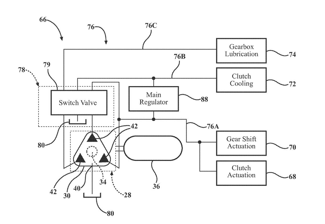
[0023]As noted above, the present invention is directed toward a multi-pressure hydraulic control system, according to the present invention and generally indicated at 66, for use with the dual clutch automatic transmission 14. The multi-pressure hydraulic control system 66 directs or otherwise controls fluid power from the outlet regions 42 of the pump 28 to the dual clutch automatic transmission 14, as described in greater detail below. It should be appreciated that the multi-pressure hydraulic control system 66 can be configured in a number of different ways to direct fluid to the dual clutch automatic transmission 14. For the purposes of clarity and consistency, unless otherwise indicated, subsequent discussion of the multi-pressure hydraulic control system 66 will refer to the multi-pressure hydraulic control system 66 as shown in FIG. 2.

[0024]Referring now to FIG. 2, one or a first embodiment of the multi-pressure hydraulic control system 66, according to the present invention...

second embodiment

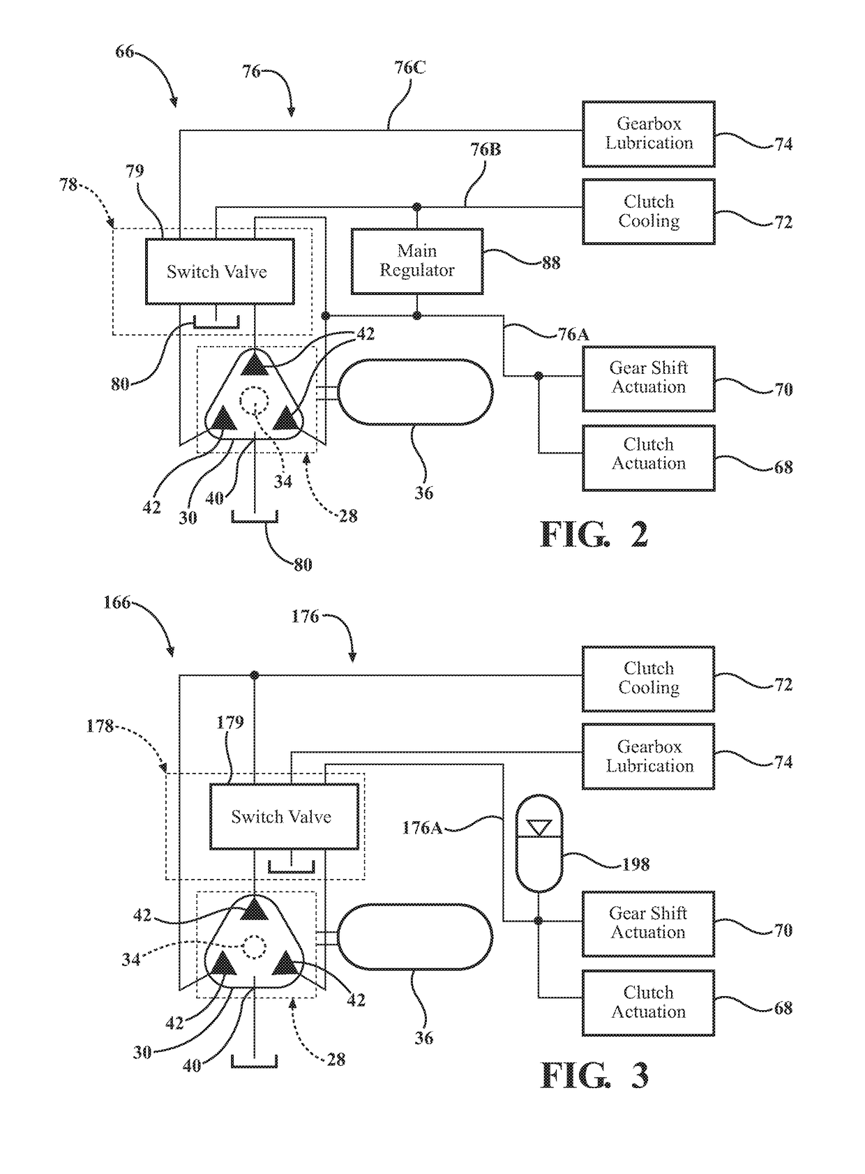
[0035]Referring now to FIG. 3, the multi-pressure hydraulic control system 166 includes the switching valve 178, fluid lines 176, and an accumulator 198 disposed in fluid communication with the fluid line 176A of the fluid lines 176 for storing pressurized hydraulic fluid. More specifically, the accumulator 198 is adapted to store hydraulic fluid under certain operating conditions of the dual clutch automatic transmission 14 so that pressurized fluid energy can subsequently be made available at the fluid line 176A under the different operating conditions. The accumulator 198 is a conventional gas-charged hydraulic accumulator, but those having ordinary skill in the art will appreciate that the accumulator 198 could be of any suitable type, or could be omitted entirely, without departing from the scope of the present invention. In one embodiment, the multi-pressure hydraulic control system 166 further includes a check valve 200 on the fluid line 176A between the switching valve 178 a...


PUM


Abstract

A multi-pressure hydraulic control system (66, 166) for use with a dual clutch automatic transmission (14) of a vehicle powertrain system (10) includes a least one pump (28) including a rotatable pump member (34), at least one inlet region (40) for receiving fluid to be pumped by the pump member (34), and at least one outlet region (42) for outputting fluid pumped by the pump member (34), and a switching valve (78, 178) receiving at least two separate outputs of fluid pumped by the at least one pump (28) for allowing the at least two separate outputs to be selectively combined and / or separated, the switching valve (78, 178) having a valve member being movable between at least three positions that produces fluid outputs having at least three fluid pressures of a high fluid pressure, a medium fluid pressure, and a low fluid pressure to one or more portions of the dual clutch automatic transmission (14).

Description

CROSS-REFERENCE TO RELATED APPLICATION(S)[0001]The present application claims priority to and all the benefits of U.S. Provisional Patent Application No. 62 / 148,778, filed on Apr. 17, 2015, which is hereby expressly incorporated herein by reference in its entirety.BACKGROUND OF INVENTION1. Field of Invention[0002]The present invention relates generally to powertrain systems and, more specifically, to a multi-pressure hydraulic control system for a dual clutch automatic transmission of a powertrain system.2. Description of the Related Art[0003]Conventional vehicle powertrain systems known in the art typically include an engine in rotational communication with a transmission. The engine generates rotational torque which is selectively translated to the transmission which, in turn, translates rotational torque to one or more wheels. The transmission multiplies the rotational speed and torque generated by the engine through a series of predetermined gear sets, whereby changing between t...

Claims


Application Information

Patent Timeline
Patent Type & Authority Applications(United States)
IPC IPC(8): F16H61/00
CPCF16H61/0025F16H2061/0037F16H61/688F16H2061/0034F16D41/08F16H61/4165F16H61/60F16H61/0021F16D2300/0214F16D2300/06F16D25/10F16D48/0206F16D2048/0266F16D2048/0233
Inventor GUO, CHENGYUNSPANGLER, CHRISTOPHER A.SEMENOV, DMITRIY
Owner BORGWARNER INC
Why Eureka
Try Eureka