
Objective lens system for endoscope

a technology of endoscope and objective lens, which is applied in the field of objective lens system for endoscope, can solve the problems of further enlarge the total length of the optical system, and achieve the effects of stable mechanical and chemically, low dispersion, and excellent shock resistance and chemical resistan

Active Publication Date: 2011-02-08
OLYMPUS CORP
View PDF14 Cites 0 Cited by
  • Summary
  • Abstract
  • Description
  • Claims
  • Application Information

AI Technical Summary

Benefits of technology

This configuration effectively corrects lateral and longitudinal chromatic aberrations while maintaining a compact optical system length, improving image quality and simplifying the lens barrel composition by optimizing ray incidence angles on the image pickup device.

Problems solved by technology

In addition, since imaging locations are generally varied due to manufacturing errors in radii of curvature and thicknesses of the lens elements, it is necessary for the objective lens systems mentioned as the conventional examples to dispose spaces between the cemented lens components and the image surfaces for adjusting the imaging locations.
Accordingly, objective lens systems which have compositions comprising cemented lens components disposed close to image surfaces like the conventional examples have a defect to further enlarge total lengths of optical systems.

Method used


Image

  • Objective lens system for endoscope
  • Objective lens system for endoscope
  • Objective lens system for endoscope

Examples


first embodiment

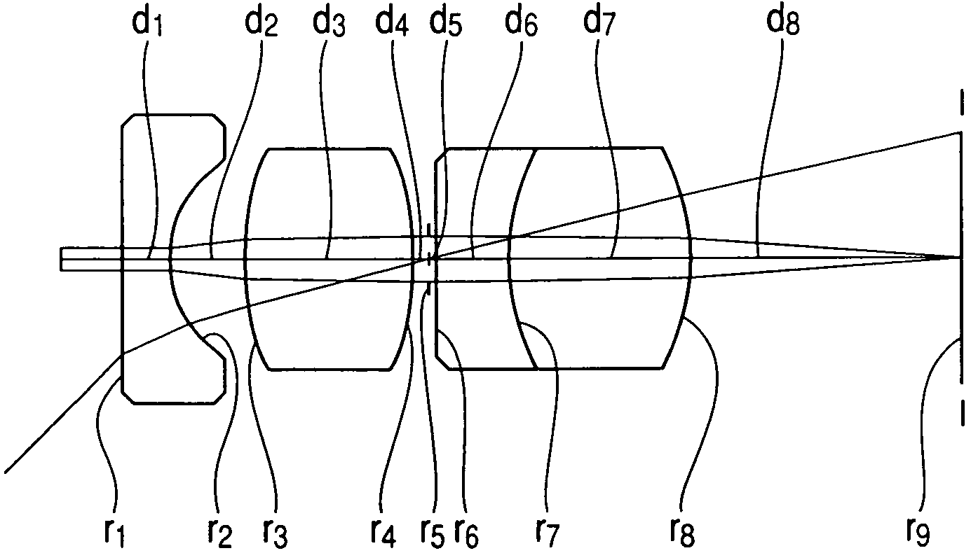
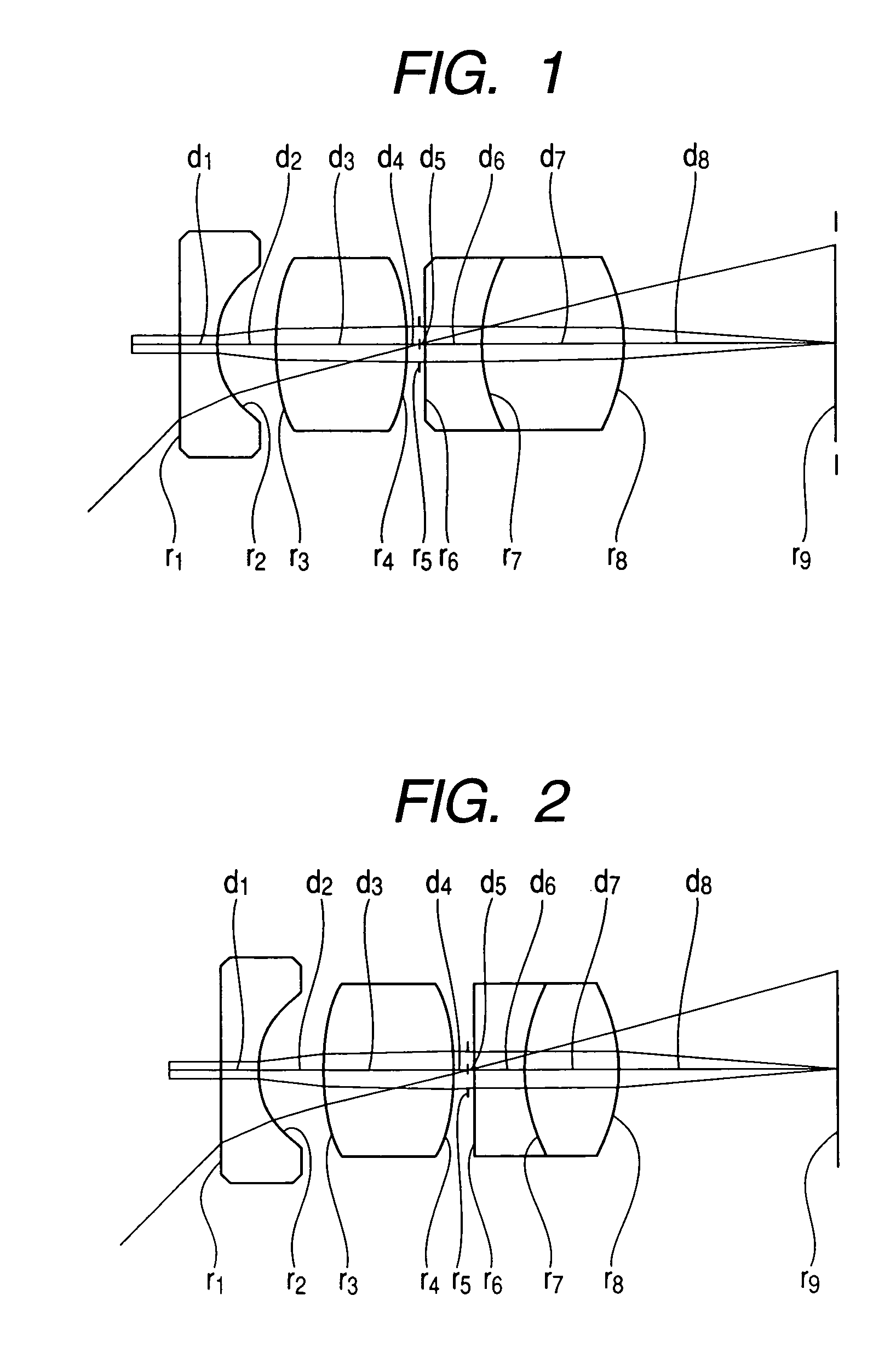
[0055]The objective lens system according to the present invention has a composition illustrated in FIG. 1, or consists of a first negative lens element (r1 to r2) which is a plano-concave lens element, a second positive lens element (r3 to r4) which is a biconvex lens element, an aperture stop (r5) and a cemented lens component consisting of a third negative lens element (r6 to r7) which is a plano-concave lens element and a fourth positive lens element (r7 to r8) which is a biconvex lens element in order from the object side. In addition, a reference symbol r9 used in FIG. 1 represents an image surface.

[0056]The first embodiment satisfies the conditions (1), (2), (5) and (4) or the conditions (1-1), (5-1) and (4-1) as shown in the above table.

second embodiment

[0057]The objective lens system according to the present invention has a composition illustrated in FIG. 2, or consists in order from the object side of a first negative lens element (r1 to r2) which is a plano-concave lens element, a second positive lens element (r3 to r4) which is a biconvex lens element, an aperture stop (r5), and a cemented lens component consisting of a third negative lens element (r6 to r7) which is a plane-concave lens element and a fourth positive lens element (r7 to r8) which is a biconvex lens element. In addition, a reference symbol r9 used in FIG. 2 represents an image surface.

[0058]The second embodiment satisfies the conditions (1), (2), (5), (4), (1-1), (2-1), (5-1) and (4-1) as shown in the above table.

third embodiment

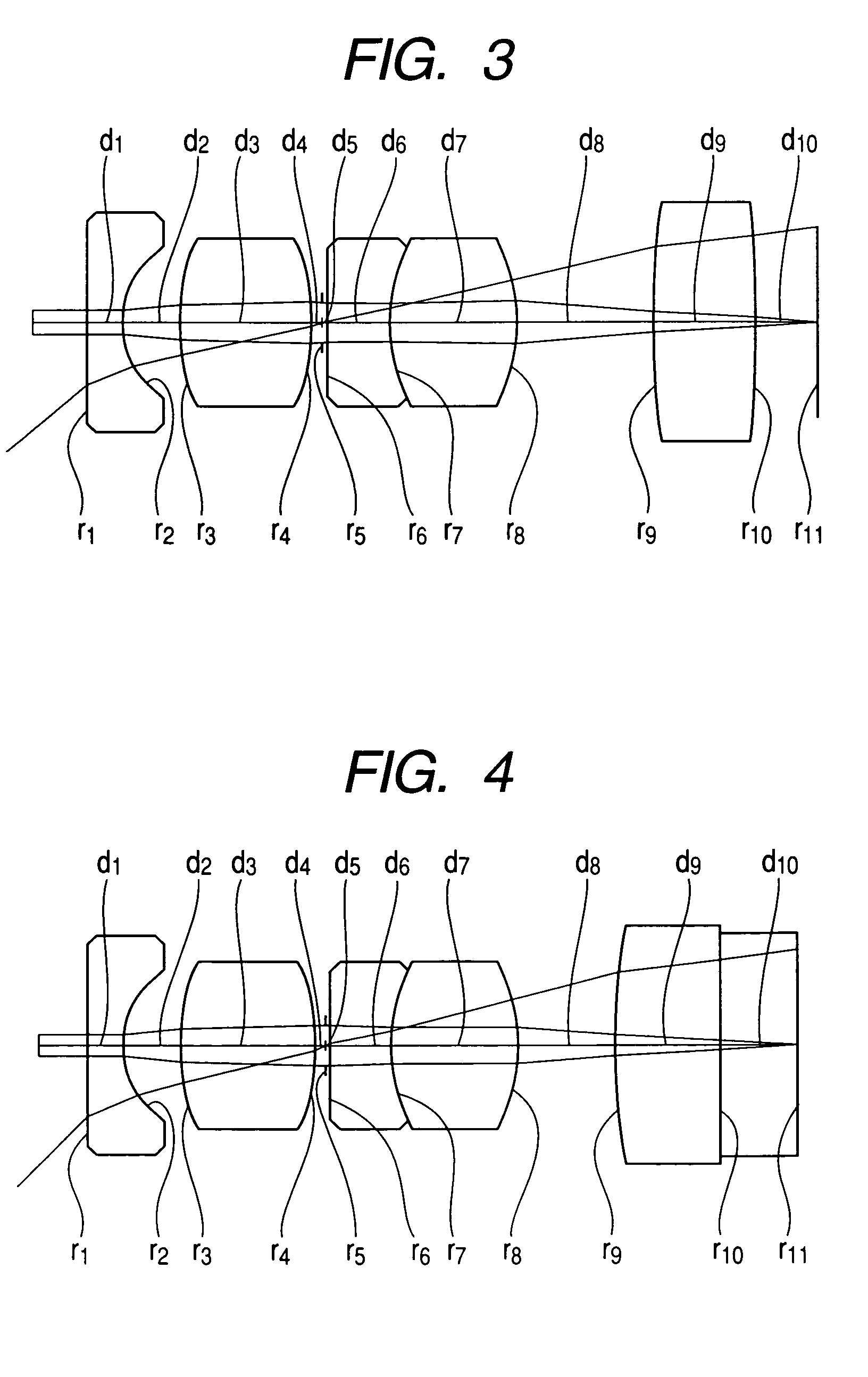
[0059]The objective lens system according to the present invention has a composition illustrated in FIG. 3, or consists of a first negative lens element (r1 to r2) which is a plano-concave lens element, a second positive lens element (r3 to r4) which is a plano-convex lens element, an aperture stop (r5), a cemented lens component consisting of a third negative lens element (r6 to r7) which is a biconcave lens element and a fourth positive lens element (r7 to r8) which is a biconvex lens element, and a fifth positive lens (r9 to r10) which is a biconvex lens element in order from the object side. By the way, a reference symbol r11 used in FIG. 3 represents an image surface.

[0060]The third embodiment satisfies the conditions (1), (2), (3) and (4) or the conditions (1-1), (3-1) and (4-1) as shown in the above table.


PUM


Abstract

An objective lens system for endoscope comprising at least a first negative lens element, a second positive lens element, an aperture stop, and a cemented lens component consisting of a third negative lens element and a fourth positive lens element, and being configured so as to satisfy the conditions (2), (5) and (4) or the conditions (2), (3) and (4) which are mentioned below, whereby the lens system corrects lateral chromatic aberration and longitudinal chromatic aberration with a good balance, favorably corrects aberrations such as chromatic aberration and has a compact composition or a short total length. D2 / f<0.9  (2) |f / (f1×&ngr;1)+f / (f2×&ngr;2)|<0.025  (5) 1.5<|(f4×&ngr;1) / (f3×&ngr;3)|  (4) |f / (f5×&ngr;5)−f / (f1×&ngr;1)−f / (f2×&ngr;2)|<0.025.  (3)

Description

BACKGROUND OF THE INVENTION[0001]The present invention relates to an objective lens system for endoscope which consists of a small number of lens elements, or has a simple composition.DESCRIPTION OF PRIOR ART[0002]In recent years in which endoscopes use larger numbers of picture elements, the endoscopes demand objective lens systems in which aberrations are favorably corrected. On the latest days, in particular, a main current is composed of objective lens systems in each of which not only Seidel aberrations are corrected favorably with a combination of several lens elements but also chromatic aberration is corrected favorably with a cemented lens components.[0003]As conventional examples of objective lens systems which use such cemented lens components, there are known objective lens systems disclosed by Japanese patent Kokai Publication No. Hei 8-27429 and Japanese Patent No. 3359092.[0004]Each of the objective lens systems disclosed by these patent bulletins is configured to comp...

Claims


Application Information

Patent Timeline
Patent Type & Authority Patents(United States)
IPC IPC(8): G02B9/34
CPCG02B23/243
Inventor INOUE, TAKAHIRO
Owner OLYMPUS CORP
Learn More