Optical wireless transmission system for performing optical space transmission, and optical transmitter used therein

a transmission system and optical wireless technology, applied in line-of-sight transmission, instruments, optical elements, etc., can solve the problems of large device size, inability to manually perform optical axis adjustment of the user's terminal, and inability to look at laser beams (infrared beams), so as to reduce the manufacturing cost of the device, reduce the size of the device, and ensure the effect of accuracy

Inactive Publication Date: 2011-02-08
PANASONIC CORP
View PDF7 Cites 28 Cited by
  • Summary
  • Abstract
  • Description
  • Claims
  • Application Information

AI Technical Summary

Benefits of technology

Therefore, an object of the present invention is to provide an optical wireless transmission system for performing high-rate data communication, which can reliably perform optical axis adjustment manually and visually and prevents a device from being made larger in size and manufacturing cost of the device from being increased, and an optical transmitter used in the optical wireless transmission system.
According to the above-mentioned present invention, since a transmission possible range of data of the optical transmitter coincides with a range in which the terminal is located when a visible beam is reflected by the optical transmitter, optical axis adjustment can be reliably performed manually and visually. In addition, since an index sensor and a light of visual confirmation are not needed, the optical wireless transmission system is made simpler in structure, a device is prevented from being made larger in size, and manufacturing cost of the device is prevented from being increased.

Problems solved by technology

However, since a semiconductor laser of excellent high-rate modulation characteristics which emits an infrared beam, or the like is generally used in the optical wireless transmission system which enables high-rate communication, a user cannot look at a laser beam (the infrared beam).
Thus, when the user performs communication while holding a terminal with his or her hand or the like, it is hard for the user to manually perform the optical axis adjustment of the terminal.
This makes a device larger in size and increases manufacturing cost of the device.

Method used


Image

  • Optical wireless transmission system for performing optical space transmission, and optical transmitter used therein
  • Optical wireless transmission system for performing optical space transmission, and optical transmitter used therein
  • Optical wireless transmission system for performing optical space transmission, and optical transmitter used therein

Examples


first embodiment

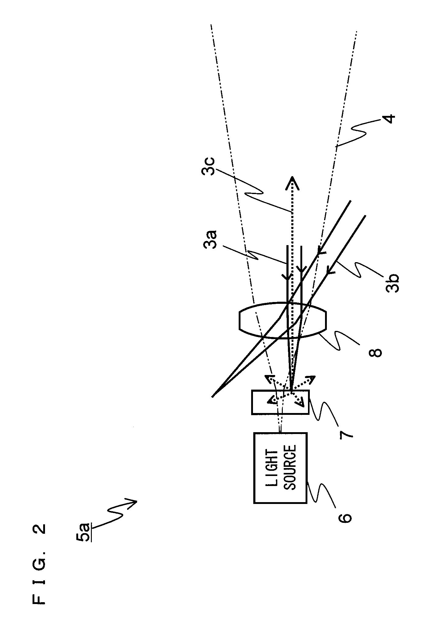
FIG. 2 is a view showing an exemplary configuration and a function of an optical transmitter 5a included in an optical wireless transmission system according to a first embodiment of the present invention. The following will describe a configuration and a function of the optical transmitter 5a which is a characterizing portion of the first embodiment with reference to FIG. 2. It is noted that although the optical space transmission apparatus 1 includes a hard disc which stores contents and the like, and a system control section which controls data transmission in addition to the optical transmitter 5a, the description thereof will be omitted in the first embodiment.

As shown in FIG. 2, the optical transmitter 5a includes a light source 6, a diffuser panel 7 as a reflection section, and a lens 8 as an incident beam restriction section. The diffuser panel 7 is provided between the light source 6 and the lens 8. A semiconductor laser of excellent high-rate modulation characteristics whi...

second embodiment

FIG. 4 is a view showing an exemplary configuration and a function of an optical transmitter 5b included in an optical wireless transmission system according to a second embodiment of the present invention. As shown in FIG. 4, the optical transmitter 5b is configured so that the lens 8 as an incident beam restriction section of the optical transmitter 5a (see FIG. 2) described in the first embodiment is replaced with a light control film 11 which is capable of setting transmission loss according to an incident angle of light. It is noted that hereinafter, the same components as those of the optical transmitter 5a of the first embodiment are designated by the same reference numerals, and the detailed description thereof will be omitted.

FIG. 5 is a front view of an example of the light control film 11. As shown in FIGS. 4 and 5, the light control film 11 includes a thin plate, and concentric circular grooves which are formed on the thin plate, and has characteristics to allow only a l...

third embodiment

FIG. 6 is a view showing an exemplary configuration and a function of an optical transmitter 5d included in an optical wireless transmission system according to a third embodiment of the present invention. As shown in FIG. 6, the optical transmitter 5d is configured so that the lens 8 of the optical transmitter 5a (see FIG. 2) described in the first embodiment is replaced with an interference filter 12 which is capable of setting transmission loss according to an incident angle of light. It is noted that hereinafter, the same components as those of the optical transmitter 5a of the first embodiment are designated by the same reference numerals, and the detailed description thereof will be omitted.

As the interference filter 12, a wavelength filter which is formed by a common dielectric multilayer film is used. In the wavelength filter, where a transmission wavelength (a reference wavelength) of a normal incident light is denoted by λ0, a transmission wavelength λ of an incident angle...


PUM


Abstract

An optical transmitter for performing high-rate data communication by means of optical space transmission is provided, which can reliably perform optical axis adjustment manually and visually, and can prevent a device from being made large in size and manufacturing cost of the device from being increased by using an simply-constructed optical transmitter. Thus, the optical transmitter of the present invention comprises an incident beam restriction section operable to allow only a visible beam which is emitted by a terminal located within a range in which an infrared beam is emitted and incident thereon to pass therethrough, a reflection section operable to reflect the visible beam which has passed through the incident beam restriction section, and a light source operable to emit the infrared beam to pass through the reflection section according to a data transmission request signal from the terminal.

Description

BACKGROUND OF THE INVENTION1. Field of the InventionThe present invention relates to an optical transmitter and an optical wireless transmission system for transmitting data to a terminal by means of optical space transmission using an infrared beam, and more particularly to an optical transmitter and an optical wireless transmission system for performing high-rate data communication by adjusting an optical axis by moving visually a terminal into a data transmission possible range of the optical transmitter.2. Description of the Background ArtAn optical wireless transmission system which performs data communication by emitting an optical beam to a free space enables wireless connection between devices such as an information processing terminal and audio visual equipment, and the like in an office and a house. Since there is no legal restriction on usage of frequency in comparison with a wireless communication system such as a wireless LAN device, UWB, and the like, the optical wirel...

Claims


Application Information

Patent Timeline
Patent Type & Authority Patents(United States)
IPC IPC(8): H04B10/00H04B10/11G02B5/02G02B5/08G02B5/28H04B10/112
CPCH04B10/1143H04B10/116
Inventor NAKASO, MARIKOSASAI, HIROYUKI
Owner PANASONIC CORP
Why Eureka
Try Eureka