Image recording system with improved clock signal transmission

a clock signal and recording system technology, applied in closed circuit television systems, color television details, television systems, etc., can solve the problems of not receiving direct clock pulse information, image-recording system is more expensive, etc., to achieve accurate synchronization of data connection, high bandwidth, and low cost of bidirectional communication.

Inactive Publication Date: 2011-02-15
ROBERT BOSCH GMBH
View PDF8 Cites 2 Cited by
  • Summary
  • Abstract
  • Description
  • Claims
  • Application Information

AI Technical Summary

Benefits of technology

[0002]The present invention makes possible an inexpensive bidirectional communication between a camera and a receiving device of an image-recording system, since only comparatively little hardware and software resources are required. In this context, it is important to weigh carefully between logical resources (big in bus systems) and hardware resources such as cable conductors and plug pins (big in two unidirectional LVDS connections). The present invention not only makes possible the control of the camera, in this instance, but an accurate synchronization of the data connection between the camera and the receiving device, which, for instance, is of great importance in an image-recording system using a stereo camera. As few as possible additional components are required for this in the camera itself, since it has to be manufactured as inexpensively as possible.
[0003]The present invention relates to the recognition that only a single pair of conductors is required for controlling the camera of the image-recording system (“uplink”). On this pair of conductors, a differential LVDS signal is coded via a pulse width modulation (PWM) in such a way that data signals and clock signals are able to be transmitted simultaneously. For the data connection between the camera and the receiving device in the direction “downlink”, on the other hand, several pairs of conductors having a separate clock signal can be used, in order to take into account the required high bandwidth. One advantage of the pulse width modulation used is that all rising sides of the signal remain equidistant, and therefore a clock pulse generation in the camera is made possible, using a PLL (phase-lock-loop) or a DLL (digital-lock-loop) circuit. One may thereby omit a quartz generator for generating the clock pulse that would otherwise be required. Furthermore, by this method, synchronous operation of the camera and the receiving device are achievable in a simple manner, since the clock signal is directly derived from the uplink signal generated in the receiving device. Also advantageously, a stereo camera having an oscillator is able to be synchronized with the aid of the clock signal derived from the uplink signal. Thus, for example, the clock signal may be used for triggering the reading out of individual lines of the images taken by the stereo camera.

Problems solved by technology

The disadvantage in the bus systems mentioned is that they do not receive any direct clock pulse information.
This, however, requires additional circuit elements, which contribute to making the image-recording system more costly.

Method used


Image

  • Image recording system with improved clock signal transmission
  • Image recording system with improved clock signal transmission

Examples


Embodiment Construction

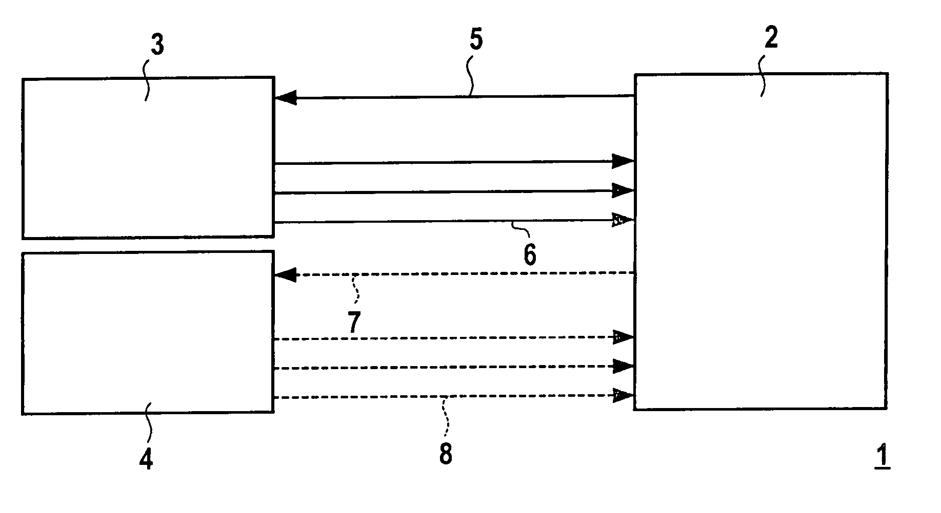
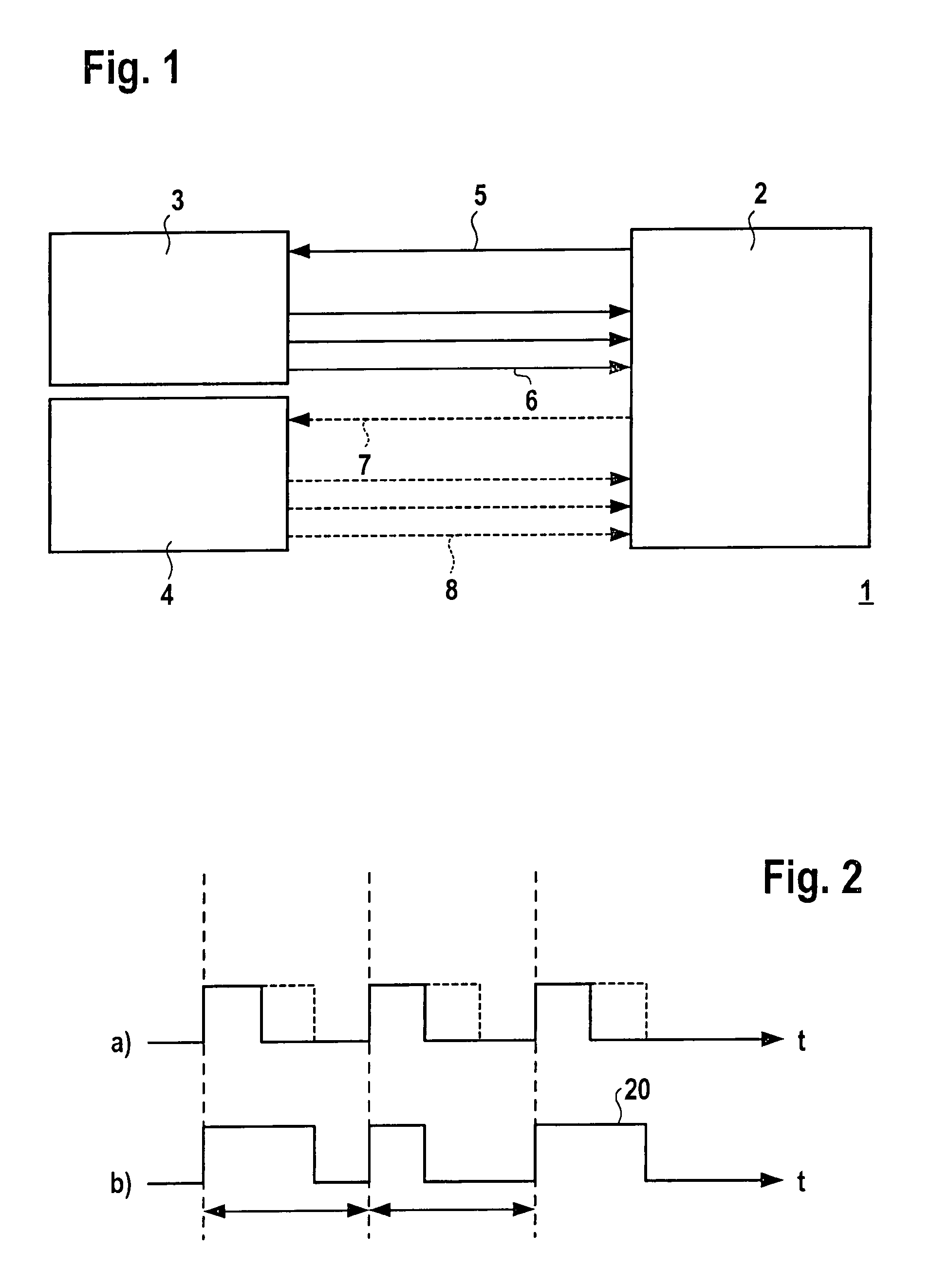
[0006]FIG. 1 shows the block diagram of an image-recording system 1. Image-recording system 1 includes at least one camera 3 and one receiving device 2. The at least one camera 3 and the receiving device 2 are connected to each other via signal connections 5, 6. In this context, signal connection 5 is a so-called “uplink” connection, that is, it makes possible a signal transmission from receiving device 2 to camera 3. In this context, signal connection 6 is a so-called “downlink” connection, that is, it makes possible a signal transmission from camera 3 to receiving device 2. The method of functioning of the image-recording system will now be described below. Receiving device 2 steadily transmits a sequence of PWM-coded (PWM=pulse-width-modulated) digital signals via signal connection 5, which, according to the illustration in FIG. 2a are made up of logical zeros or logical ones. In the illustration in FIG. 2a, a continuous line represents a logical zero, while the dotted line means...


PUM


Abstract

An image-recording system having at least one camera, having a receiving device and having a signal connection between the camera and the receiving device. The receiving device generates a PWM-coded signal which is transmitted to the camera. A clock signal is obtained in the camera from the PWM-coded signal.

Description

BACKGROUND INFORMATION[0001]The image-recording system is preferably to be used in motor vehicles. Image-recording systems for this type of application have to be designed to be particularly robust and cost-effective. In one image-recording system that includes a camera having a digital interface, the image data gathered by the camera are usually passed on, via a rapid serial connection, to the receiving device (“downlink”) if the latter is spatially at a distance from the camera. A control unit that further processes these image data, or is controlled by the image data, comes into consideration as the receiving device. For communication between the receiving device and the camera, transmission of data in the direction of the camera (“uplink”) is also necessary. In comparison to the data transmission between the camera and the receiving device, in this context, the required bandwidth is very low, since essentially only control signals and no image data have to be transmitted. In ord...

Claims


Application Information

Patent Timeline
Patent Type & Authority Patents(United States)
IPC IPC(8): H04N7/18H04N5/073H04N5/232
CPCH04N5/0733H04N5/23203H04N23/66
Inventor STUMBER, TOBIASFRITZ, STEFFEN
Owner ROBERT BOSCH GMBH
Why Eureka
Try Eureka