Fusing unit and image forming apparatus using the same

a technology of fusing unit and forming apparatus, which is applied in the direction of electrographic process apparatus, instruments, optics, etc., can solve the problems of increasing production costs, slow warm-up, and limited expansion of the external diameter of the fusing roller b>3/b> and the pressing roller b>5/b>, so as to secure the stability of the fusing and enhance heat efficiency

Active Publication Date: 2011-02-15
HEWLETT PACKARD DEV CO LP
View PDF11 Cites 9 Cited by
  • Summary
  • Abstract
  • Description
  • Claims
  • Application Information

AI Technical Summary

Benefits of technology

[0016]Accordingly, aspects of the present invention provide a fusing unit which secures fusing stability with respect to a printing medium that is rapidly moved, and enhances heat efficiency without enlarging an overall size, and an image forming apparatus using the same.
[0018]According to an aspect of the invention, the nip plate further includes a heat absorbing layer which is formed on a surface thereof facing the heat source and enhances a heat absorption rate.

Problems solved by technology

However, expanding the external diameters of the fusing roller 3 and the pressing roller 5 is limited given consideration of the overall size of the image forming apparatus.
Also, the expansion causes slower warm-up and raises production costs.

Method used


Image

  • Fusing unit and image forming apparatus using the same
  • Fusing unit and image forming apparatus using the same
  • Fusing unit and image forming apparatus using the same

Examples


Embodiment Construction

[0036]Reference will now be made in detail to the present embodiments of the present invention, examples of which are illustrated in the accompanying drawings, wherein like reference numerals refer to the like elements throughout. The embodiments are described below in order to explain the present invention by referring to the figures.

[0037]A fusing unit according to an example embodiment of the present invention is formed on a printing path of an image forming apparatus, and fuses a toner image transferred to a printing medium.

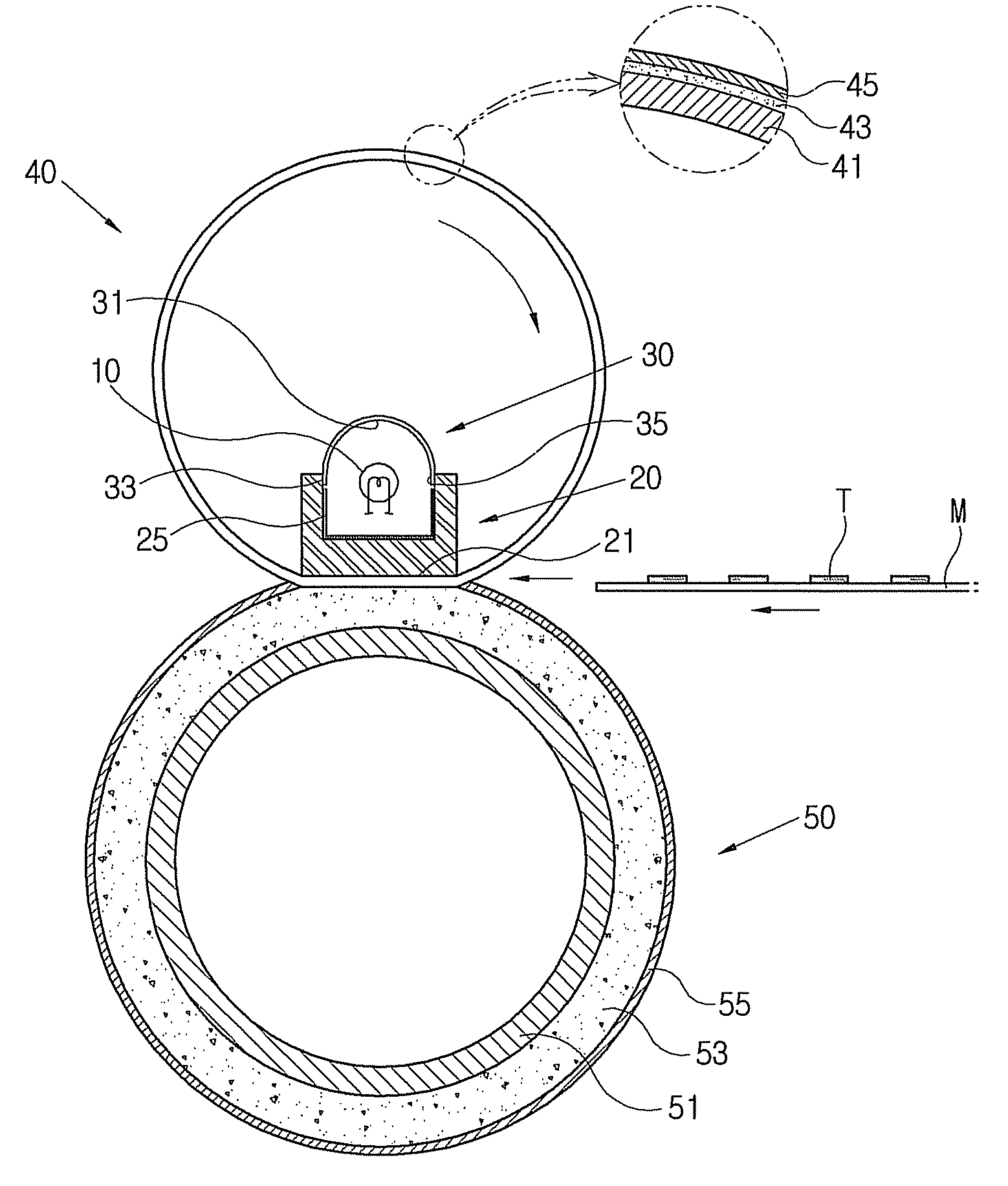
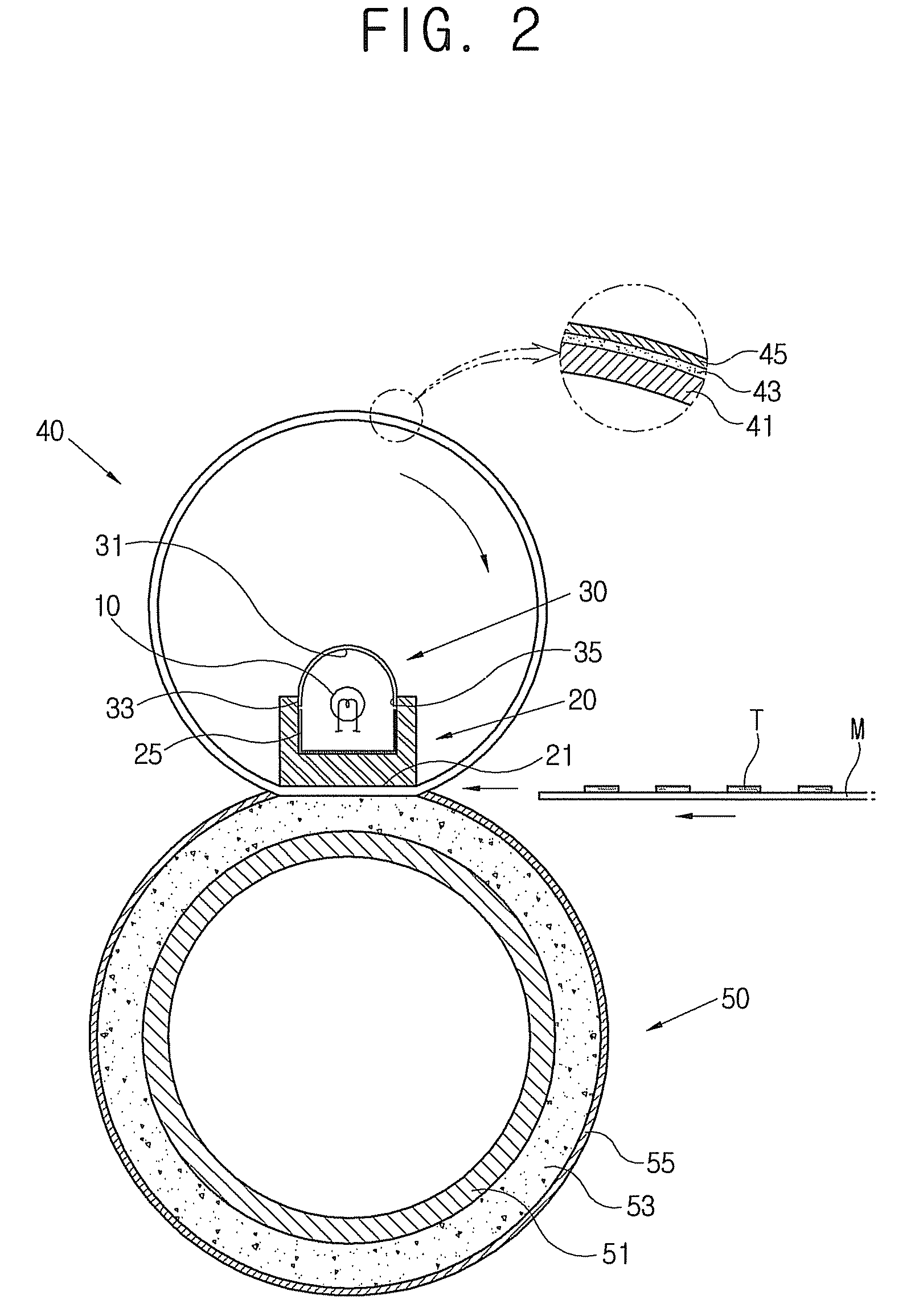
[0038]As shown in FIG. 2, a fusing unit according to an example embodiment of the present invention includes a heat source 10, a nip plate 20, a reflection member 30, a belt member 40 and a driving roller 50.

[0039]The heat source 10 generates radiant heat to heat the nip plate 20. The heat source 10 may include a lamp, e.g., a halogen lamp or a resistance heating element, which is provided in a space on the nip plate 20. The nip plate 20 is heated by the heat...


PUM


Abstract

A fusing unit is formed along a printing path in an image forming apparatus and fuses an image transferred to a printing medium. The fusing unit includes: a heat source; a nip plate which is heated by the heat source, and includes a nip part to heat and press the printing medium; and a reflection member to reflect heat generated by the heat source toward the nip part. A belt member is rotatably provided about the heat source, the nip plate and the reflection member, and guides the movement of the printing medium. A driving roller faces the nip part and rotatably drives the belt member. The nip plate and the driving roller form a fusing nip, which quickly heats and provides for quick fusing of a toner image to a printing medium.

Description

CROSS-REFERENCE TO RELATED APPLICATIONS[0001]This application claims the benefit of Korean Patent Application No. 2007-17143, filed Feb. 20, 2007, in the Korean Intellectual Property Office, the disclosure of which is incorporated herein by reference.BACKGROUND OF THE INVENTION[0002]1. Field of the Invention[0003]Aspects of the present invention relate to a fusing unit which heats and fuses an image transferred to a printing medium, and an image forming apparatus using the same; and more particularly, to a fusing unit which intensively heats a fusing part and enhances heat efficiency, and an image forming apparatus using the same.[0004]2. Description of the Related Art[0005]Generally, an electrophotographic image forming apparatus scans light to a photosensitive body which is charged to a predetermined electric potential to form an electrostatic latent image, and develops the image with a predetermined toner to transfer and fuse the image on a printing medium, thereby printing an im...

Claims


Application Information

Patent Timeline
Patent Type & Authority Patents(United States)
IPC IPC(8): G03G15/20
CPCG03G15/2039G03G2215/2035G03G15/2053G03G15/2064
Inventor LEE, SEUNG-JUNSEOL, DONG-JINKANG, DONG-KYUN
Owner HEWLETT PACKARD DEV CO LP
Why Eureka
Try Eureka