
High power fuse terminal with scalability

a high-power fuse and terminal technology, applied in the direction of coupling device details, coupling contact members, coupling device connections, etc., can solve the problems of reducing electrical conductivity, reducing the conductivity of copper, and prone to relaxation, so as to achieve higher relaxation temperature and higher conductivity

Active Publication Date: 2011-02-22
LEAR CORP
View PDF26 Cites 129 Cited by
  • Summary
  • Abstract
  • Description
  • Claims
  • Application Information

AI Technical Summary

Problems solved by technology

However, copper is susceptible to relaxation (i.e., loss of spring force) as the temperature increases.
Relaxation of the female terminals decreases the overall contact area with the male blades, resulting in reduced electrical conductivity, increased resistance, and a further increase in temperature.
Therefore, the spring force cannot be further increased by simply making the terminals thicker or wider.
When copper is used, the size limitations may make the desired spring force unattainable.
On the other hand, copper alloys typically have a lower conductivity.
In automotive applications, fuses using copper alloys are typically limited to 60 amps or less.

Method used


Image

  • High power fuse terminal with scalability
  • High power fuse terminal with scalability
  • High power fuse terminal with scalability

Examples


Embodiment Construction

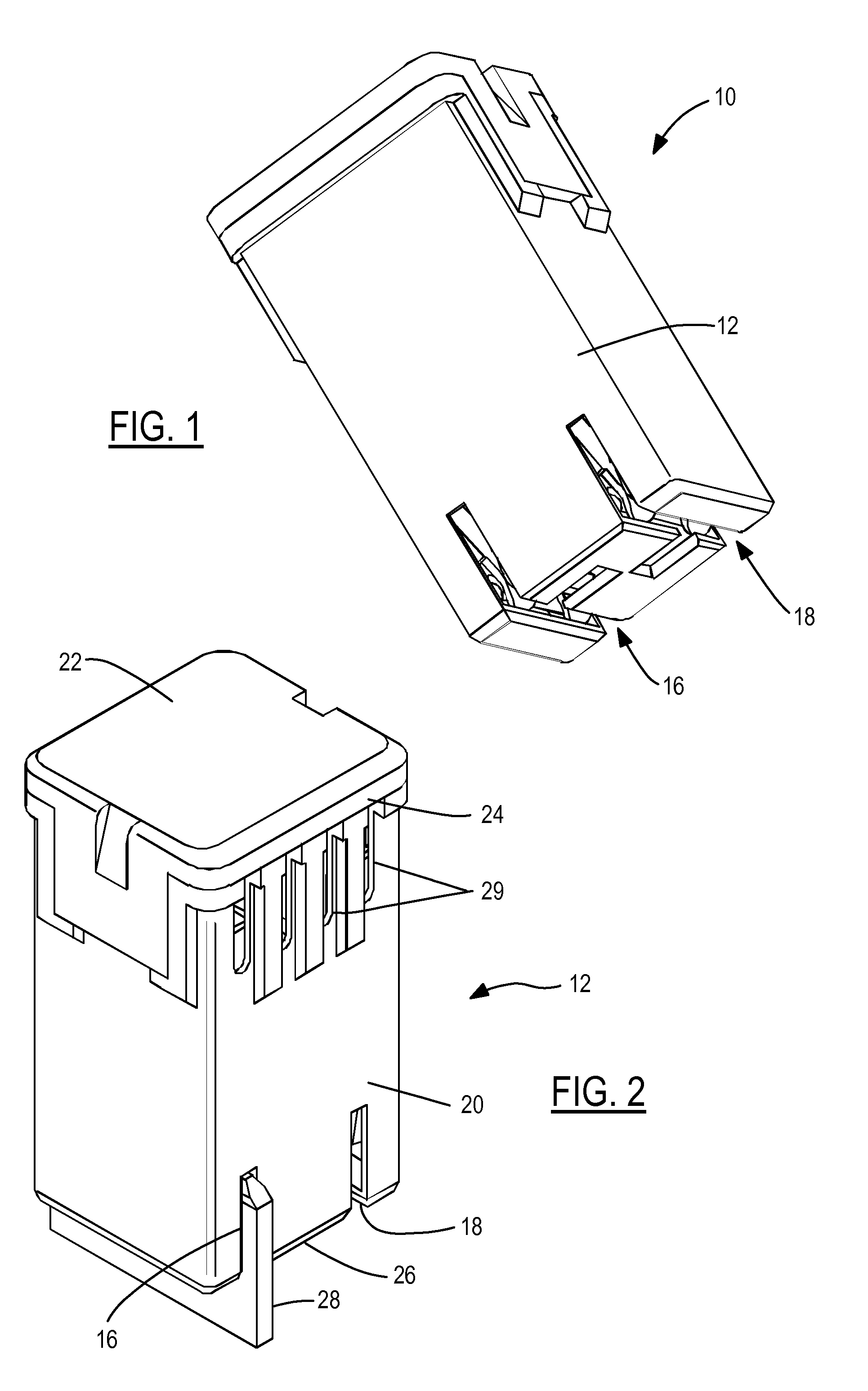
[0022]Referring now to the drawings, there is illustrated in FIG. 1 a high power fuse shown generally at 10. The high power fuse 10 includes a housing 12 and a fuse assembly 14 disposed within the housing 12. The housing 12 includes a first slot 16 for receiving a first terminal blade and a second slot 18 for receiving a second terminal blade.

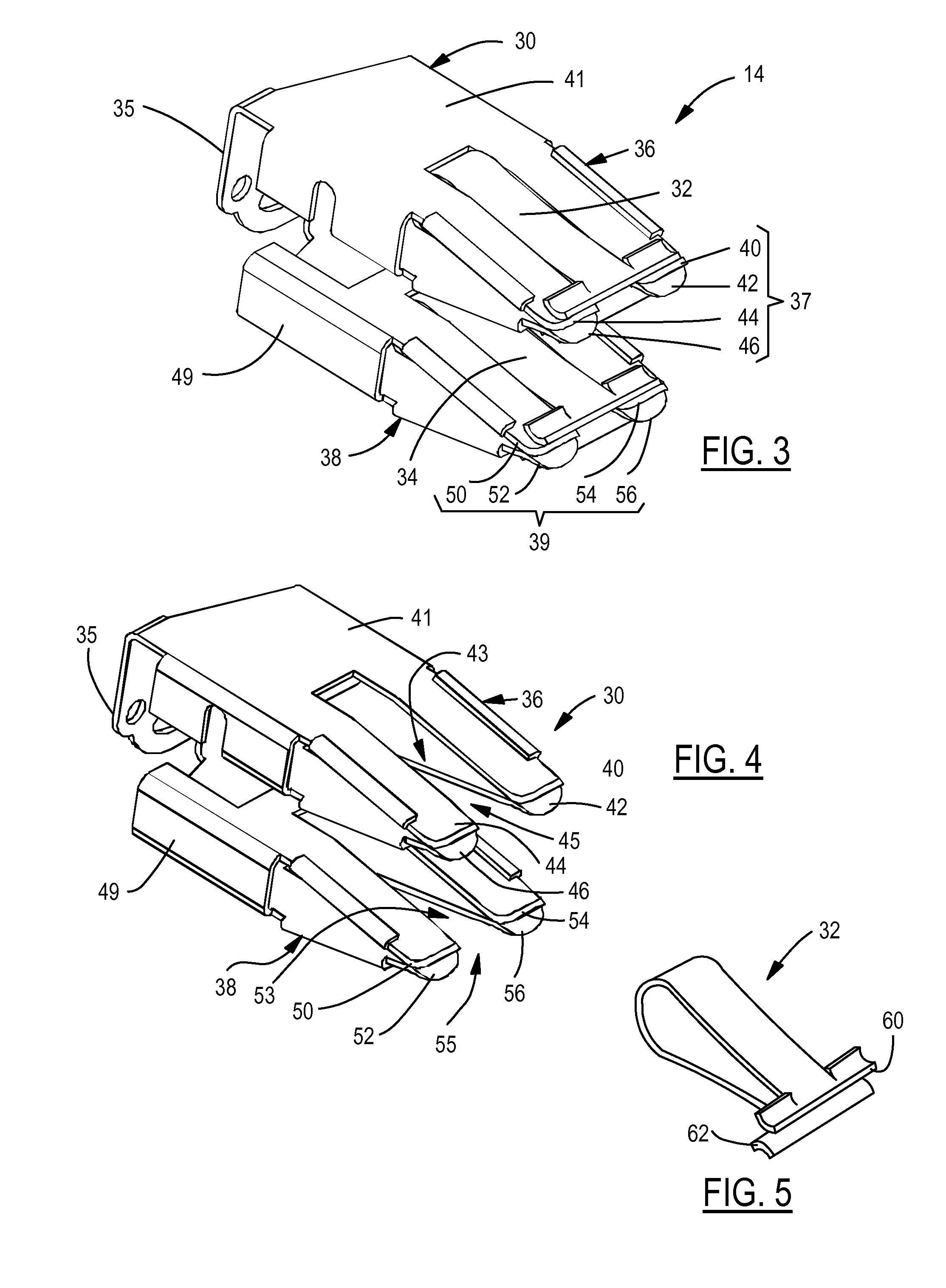
[0023]FIG. 2 is a perspective view of the housing 12. The housing 12 is preferably produced from two sections that include a body portion 20 and a lid portion 22. The body portion 20 is an elongated chamber that includes an open end 24 and a closed end 26. The open end 24 is of a sufficient width and length for receiving and housing the fuse assembly 14 (shown in FIG. 3) within the housing 12. The first slot 16 and the second slot 18 are formed in the closed end 26. The slots are aligned with respective receiving members for making an electrical connection with a respective terminal blade (shown generally at 28).

[0024]The lid portion 22 attache...


PUM


Abstract

A female terminal receptor for an automotive fuse or a terminal includes three or more pairs of opposing beams and at least one U-shaped clamping member. The U-shaped clamping member has a first base portion laterally disposed between two pairs of opposing beams and at least one pair of first end portions disposed over at least one pair of opposing beams for applying a predetermined compression force. The opposing beams have a first metallic composition and the U-shaped clamping member has a second metallic composition, wherein the first metallic composition has a higher conductivity than the second metallic composition, and wherein the second metallic composition has a higher relaxation temperature than the first metallic composition.

Description

CROSS REFERENCE TO RELATED APPLICATIONS[0001]The present application claims priority to provisional application Ser. No. 61 / 187,887, filed Jun. 17, 2009, entitled “High Power Terminal; Scaleable Design.”STATEMENT REGARDING FEDERALLY SPONSORED RESEARCH[0002]Not Applicable.BACKGROUND OF THE INVENTION[0003]The present invention relates in general to terminals for high power automotive fuses and electrical connectors, and, more specifically, to a scalable terminal design for adjusting current-carrying capacity.[0004]High-power fuse assemblies for power distribution boxes used in automotive vehicles commonly include a fuse body with a nonconductive housing encasing a conductive set of female terminals. The set of female terminals are each connected to a respective end of a fuse element retained in the housing. The female terminals are inserted over a set of male blade terminals extending from a power distribution box for completing an electrical circuit. The female terminals are typicall...

Claims


Application Information

Patent Timeline
Patent Type & Authority Patents(United States)
IPC IPC(8): H01R13/15
CPCH01R9/245H01R13/68H01R13/112H01R13/03
Inventor PAVLOVIC, SLOBODANMENZIES, DAVIDGLICK, MICHAEL
Owner LEAR CORP
Learn More