

Rechargeable high power electrochemical device
a high-power, electrochemical technology, applied in the direction of sustainable manufacturing/processing, flat cell grouping, secondary cell details, etc., can solve the problems of poor power supply and transient power loss, adverse impact on electronic equipment, and especially sensitive electric and electronic devices. to achieve the effect of high power upon demand
- Summary
- Abstract
- Description
- Claims
- Application Information
AI Technical Summary
Benefits of technology
Problems solved by technology
Method used
Image

Examples
example 1
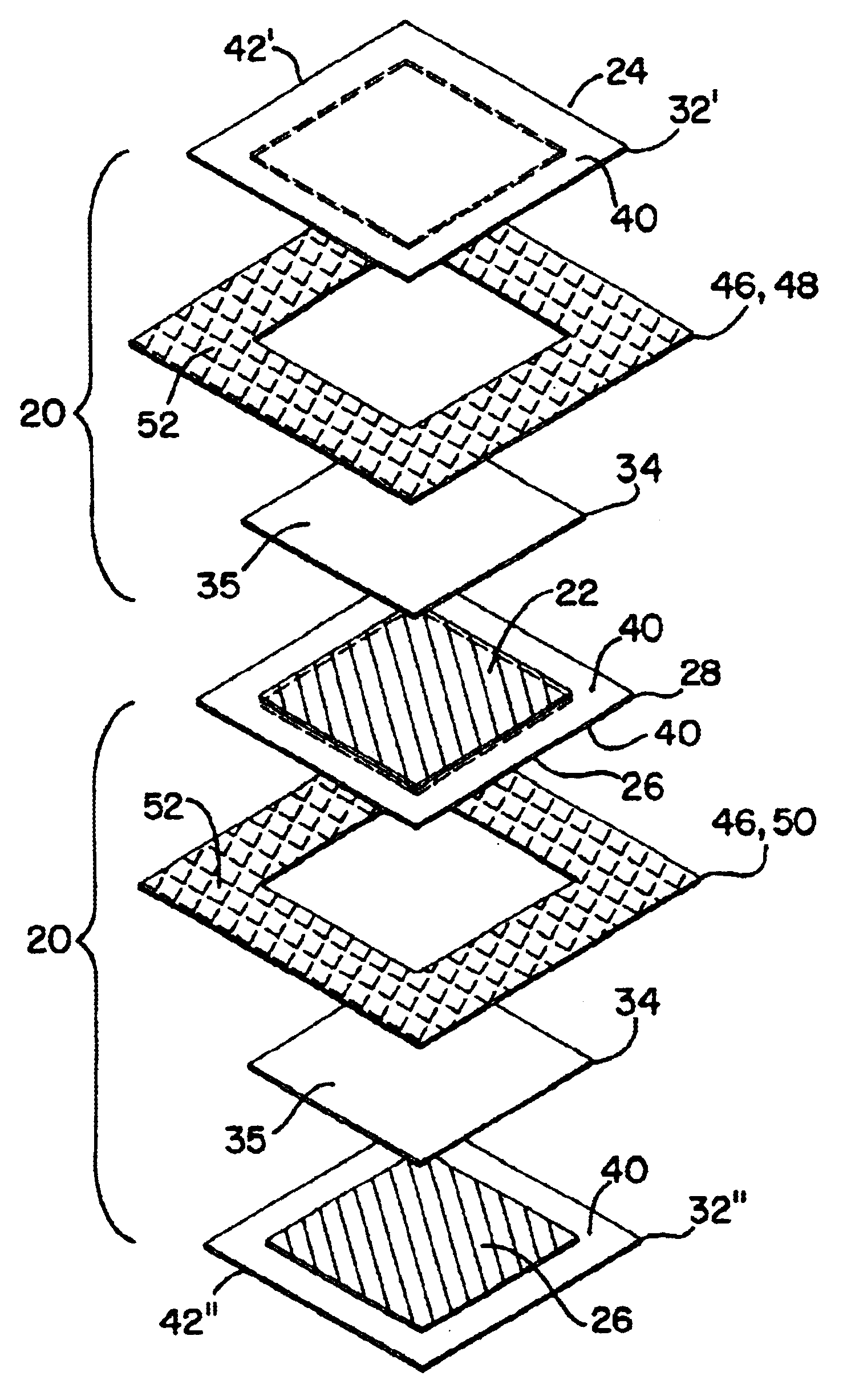
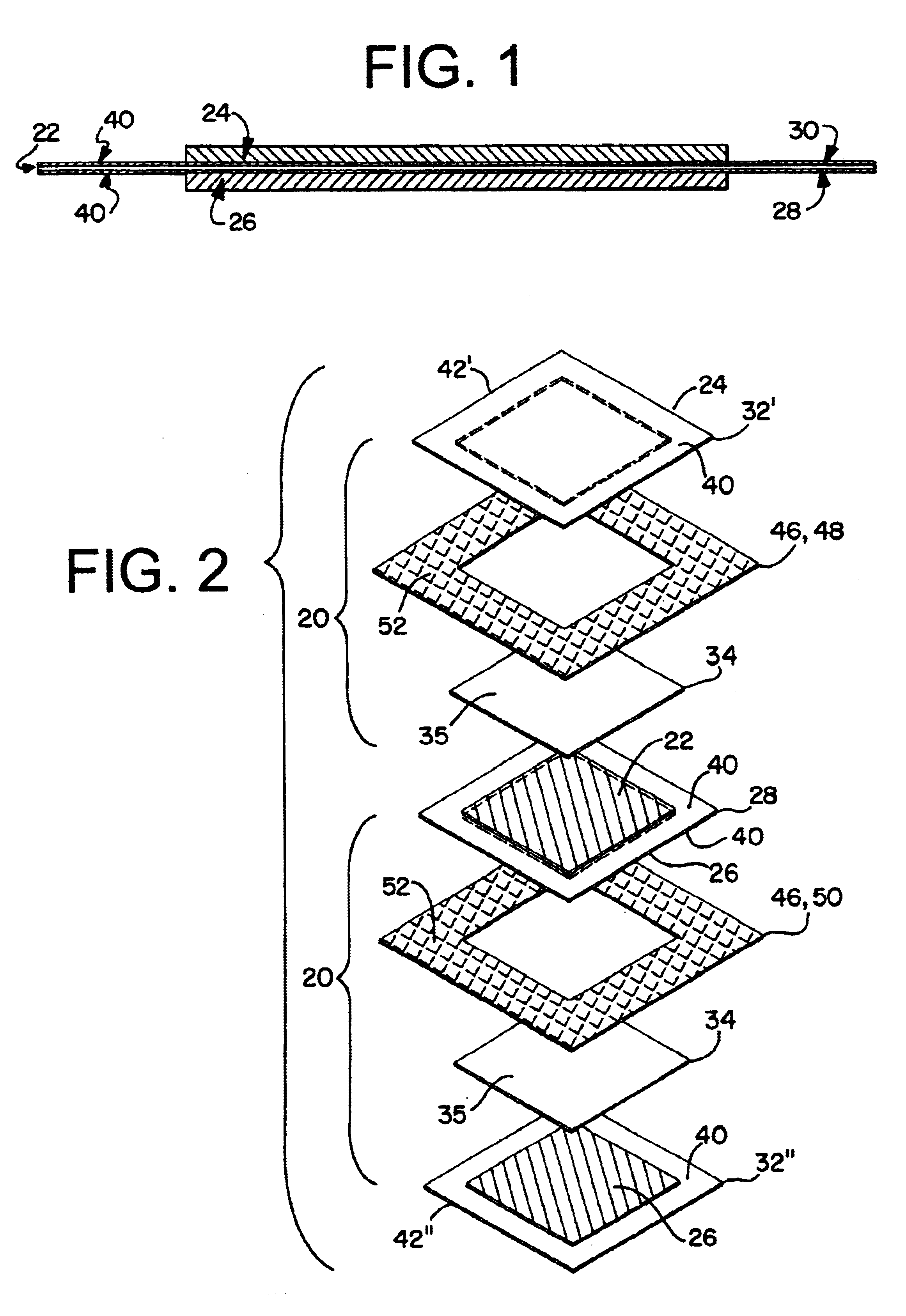
[0076]The above anode end plate, cathode end plate and bipolar plate were first combined into stackable electro chemical cells. First, 6 frames of SURLYN® 1652 film (DUPONT®) of 80 μm thickness were die-cut with 140×140 mm2 outer dimension and 102×102 mm2 inner dimension. To each side of the anode and cathode end plate and bipolar plate structures discussed above, a frame was attached by using a commercially available heated press. The cathode end plate and the bipolar plate, with their respective frames, were laid on a flat surface with the cathode facing upward. An 110×110 mm2 piece of microporous polyolefinic separator was positioned on top of each of the two cathode layers and partially over the frames of the corresponding plate. For each of the two plates, the separator was then heat-welded to the frame on two opposite sides. The bipolar plate was then stacked on top of the cathode end plate, followed by the anode end plate, according to FIG. 2. Three sides of the 2-cell stack ...
example 2
[0078]Another battery was assembled according to the above description, with slight alterations to create a higher-power device. Specifically, 9 bipolar plates were used instead of one only. This procedure resulted in a 10-cell bipolar monolithic unit of 25 V nominal voltage and 119 g weight, which was mounted in the same way in a compression device at about 1 kg / cm2 compression.
[0079]FIG. 7 shows the power performance of the 10-cell unit during 10 seconds discharge pulses of 0.1 W / cm2, i.e. at a constant power rate of 100W, at an ambient temperature of 22° C. The battery was kept at open circuit for 5 minutes in between pulses. The performance of the battery during this test was excellent, considering that the discharge current density was as high as 0.07 A / cm2. The power density of this non-optimized device approached 1000 W / kg.
example 3
[0080]After performing the high power discharge test as described above, the mechanical compression was briefly released in order to fit two Type K thermocouples in between the two end plates and the two nickel foam mats. The compression device was then tightened to about 0.3 kg / cm2, as assessed by a PRESSUREX®-micro pressure sensitive mat purchased from Sensor Products Inc.
[0081]In order to assess safety performance of the battery device of the present invention, the new device with the thermocouples was tested during a full short circuit according to UL® battery safety standard 2054. Such an extreme abuse condition should not happen during any application since the battery device of the present invention is protected electrically and electronically. However, the abuse test evaluates the unlikely case that all electric and electronic safety features of the battery system fail or have been disconnected purposely.
[0082]The battery of the present example was initially at ambient tempe...
PUM
| Property | Measurement | Unit |
|---|---|---|
| porosity | aaaaa | aaaaa |
| porosity | aaaaa | aaaaa |
| voltage | aaaaa | aaaaa |
Abstract
Description
Claims
Application Information