Method and apparatus for using collimated and linearly polarized millimeter wave beams at Brewster's angle of incidence in ground penetrating radar to detect objects located in the ground

a technology of collimated and linear polarized millimeter wave beams and radars, applied in the field of methods and apparatus for identifying objects, can solve the problems of tunneling, tunnel depth, and currently available techniques that do not have the depth range and resolution needed to detect tunnels at the deeper end of this depth rang

Inactive Publication Date: 2011-02-22
THE BOEING CO
View PDF40 Cites 33 Cited by
  • Summary
  • Abstract
  • Description
  • Claims
  • Application Information

AI Technical Summary

Problems solved by technology

A threat is posed by tunneling.
Tunnels may be deeply bored.
Currently available techniques do not have the depth range and resolution needed to detect tunnels at the deeper end of this depth range.

Method used


Image

  • Method and apparatus for using collimated and linearly polarized millimeter wave beams at Brewster's angle of incidence in ground penetrating radar to detect objects located in the ground
  • Method and apparatus for using collimated and linearly polarized millimeter wave beams at Brewster's angle of incidence in ground penetrating radar to detect objects located in the ground
  • Method and apparatus for using collimated and linearly polarized millimeter wave beams at Brewster's angle of incidence in ground penetrating radar to detect objects located in the ground

Examples


Embodiment Construction

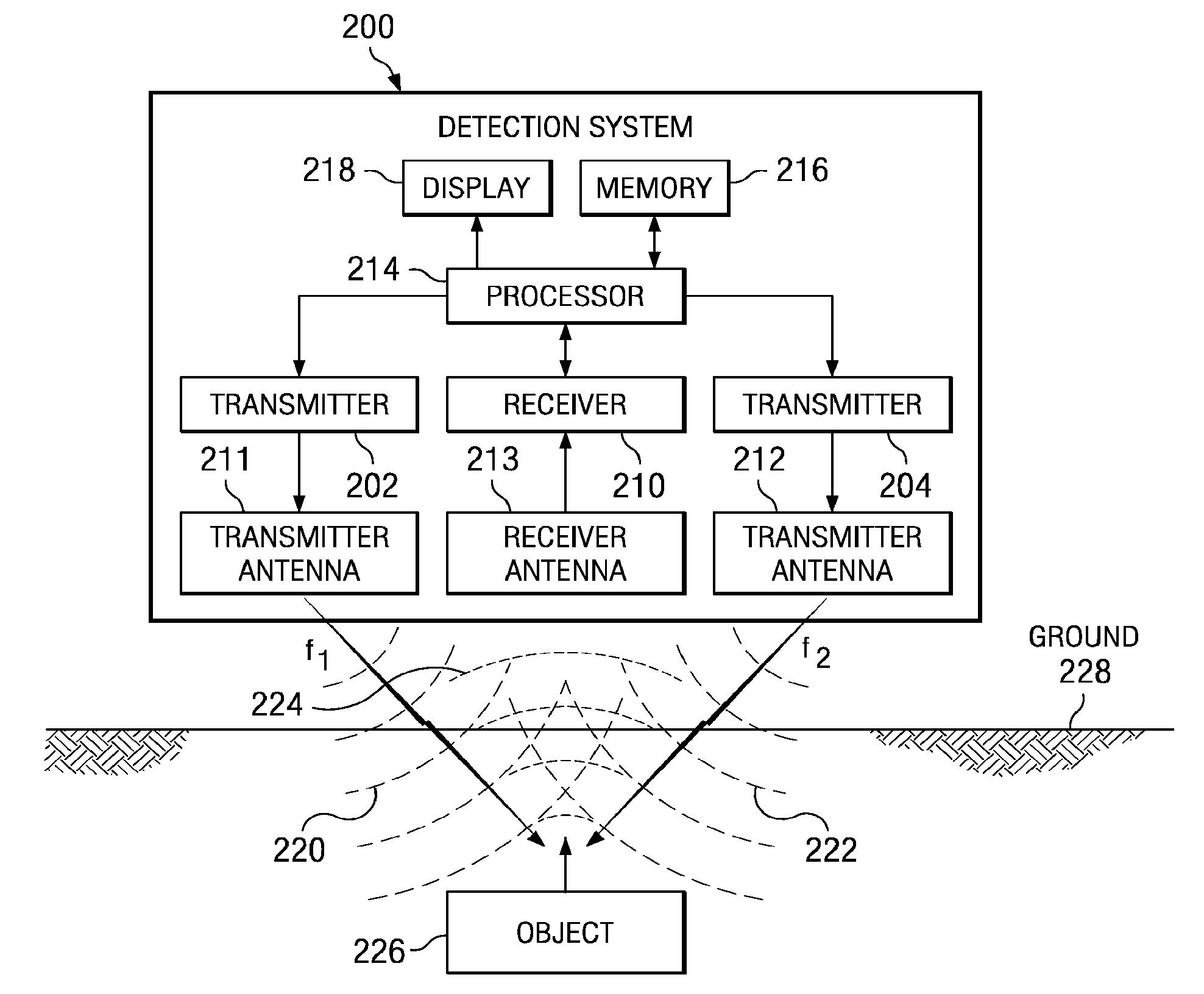
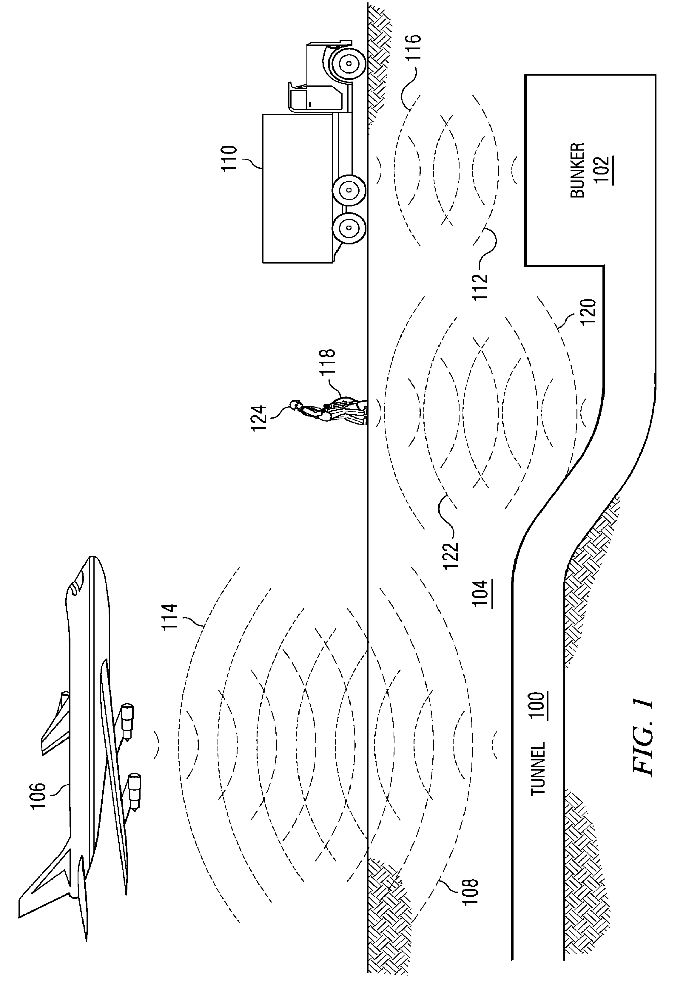
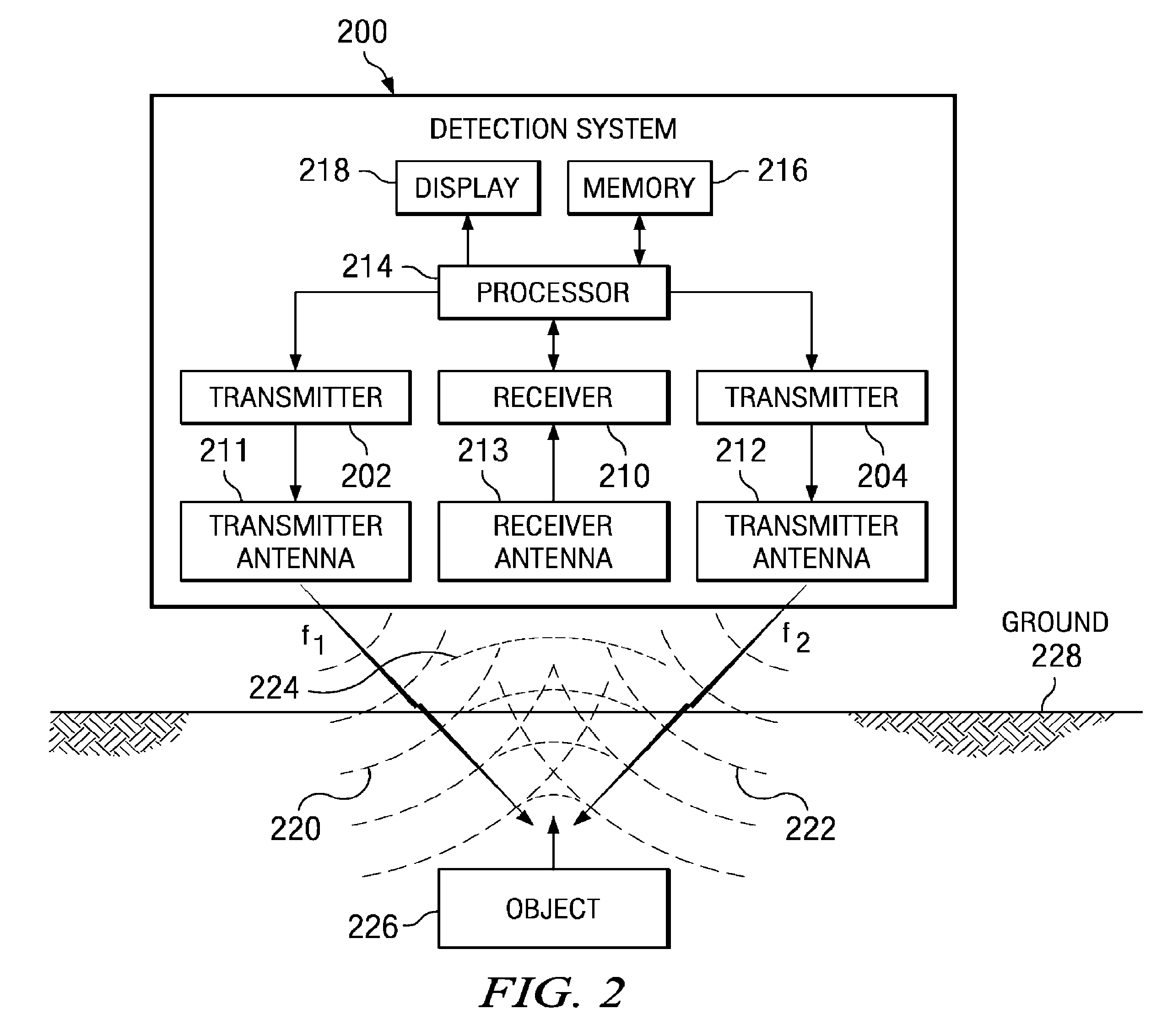
[0023]With reference now to the figures and in particular with reference to FIG. 1, a diagram illustrating a method and apparatus for detecting structures buried under the ground is depicted in accordance with an advantageous embodiment. In these illustrative examples, non-linear ground penetrating radar technology is used to detect objects, such as tunnels and bunkers.

[0024]In the depicted example, electromagnetic pulses are launched into the ground and echoes from an underground object are received and interpreted in an attempt to identify the object. The different illustrative embodiments recognize that a problem with this current method of using ground penetrating radar is that finding an appropriate radio frequency to operate the system is often difficult. The different embodiments recognize that this difficulty lies in the contradictory capabilities and limitations of low and high frequencies.

[0025]The different advantageous embodiments recognize that electromagnetic technique...


PUM


Abstract

A detection system comprises a transmitter unit, a receiver, and a processor. The transmitter unit is capable of transmitting a first collimated beam having a first frequency and a second collimated beam having a second frequency into a ground, wherein the first collimated beam and the second collimated beam overlap in the ground. The receiver is capable of monitoring for a response radio frequency signal having a frequency equal to a difference between the first frequency and the second frequency. The response radio frequency signal is generated by an object having non-linear conductive characteristics in response to receiving the first collimated beam and the second collimated beam. The processor is capable of controlling an operation of the transmitter unit and the receiver. The processor is connected to the transmitter unit and the receiver. The object is detected when the response radio frequency signal is detected by the receiver.

Description

CROSS REFERENCE TO RELATED APPLICATION[0001]The present invention is a continuation-in-part (CIP) of the following patent application: entitled “Method and Apparatus for Using Non-Linear Ground Penetrating Radar to Detect Objects Located in the Ground”, Ser. No. 11 / 758,785, filed Jun. 6, 2007, and incorporated herein by reference. The present invention is also related to the following patent application: entitled “Method and Apparatus for Locating Objects Using Radio Frequency Identification”, Ser. No. 11 / 758,787, filed Jun. 6, 2007, and incorporated herein by reference.BACKGROUND INFORMATION[0002]1. Field[0003]The present invention relates generally to improved method and apparatus for identifying objects. Still more particularly, the present invention relates to a method and apparatus for detecting objects located in the ground using electromagnetic radiation.[0004]2. Background[0005]An increasing demand is present for an approach to detect and locate tunnels, underground infrastr...

Claims


Application Information

Patent Timeline
Patent Type & Authority Patents(United States)
IPC IPC(8): G01S13/04G01S13/88G01V3/12G01S13/00G01V3/00
CPCG01S13/04G01S13/87F41H11/136G01V3/12G01S13/885
Inventor HOLLY, SANDORKOUMVAKALIS, NICHOLASSMITH, ROBERT ALAN
Owner THE BOEING CO
Why Eureka
Try Eureka