Input device

a technology of input device and switch position, which is applied in the direction of input/output for user-computer interaction, instruments, computing, etc., can solve the problems of unavoidable change of the design of the controller for detecting the switch signal, noise is liable to occur, and the wiring of the signal lines corresponding to the switch elements is more difficult to design, so as to improve the detection accuracy of the switch position

Inactive Publication Date: 2011-02-22
ALPS ALPINE CO LTD
View PDF8 Cites 69 Cited by
  • Summary
  • Abstract
  • Description
  • Claims
  • Application Information

AI Technical Summary

Benefits of technology

[0014]According to the present invention, the number of switch signal lines is smaller than the number of push switch elements, and the coordinate data is used to determine which push switch element is enabled although the position of the enabled switch cannot be identified from the switch signal lines. This contributes to reduction in size of the input device. It is not necessary to change the controller design. Moreover, an input device with less noise can be realized.
[0018]When an operator presses an operation surface, the operator may unintentionally press a point different from the desired point on the operation surface due to his / her pressing habit, etc., and incorrect coordinate data may therefore be output. In this case, an error signal indicating that a switch element that is not enabled has been pressed may be output. In particular, when the space between the switch elements is narrow, an error signal indicating that the switch adjacent to the enabled switch has been pressed may be output. Preferably, for example, the coordinate data received from the primary input unit is compensated for variations in the coordinate data by averaging a plurality of previously received coordinate data to improve the detection accuracy of the switch position.
[0019]The primary input unit may be, for example, an electrostatic-capacitance sensor. Electrostatic-capacitance sensors may, in particular, cause positional deviation of the coordinate data. The coordinate data corrector is effective to improve the detection accuracy of the switch position.

Problems solved by technology

Thus, the larger the number of switch elements 11 is, the more difficult it is to design the wiring of the signal lines corresponding to the switch elements 11 in the input device within a limited space.
It is also unavoidable to change the design of a controller for detecting switch signals when the number of switch elements 11 changes.
The switch signal lines individually provided for the switch elements 11 experience another problem in that noise is liable to occur.

Method used


Image

  • Input device
  • Input device
  • Input device

Examples


Embodiment Construction

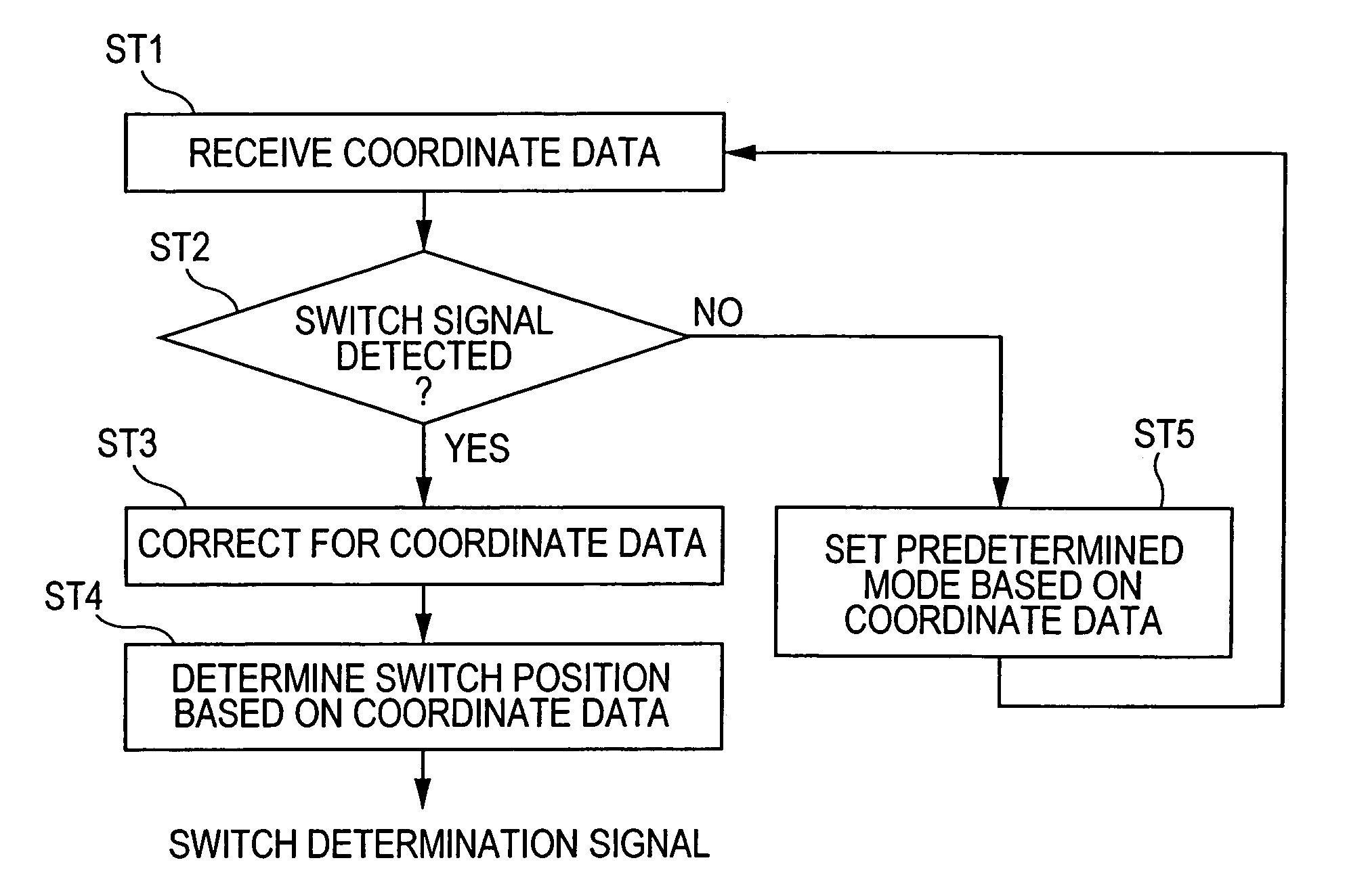
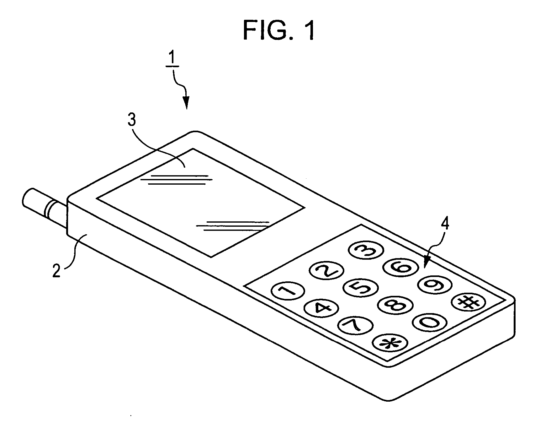
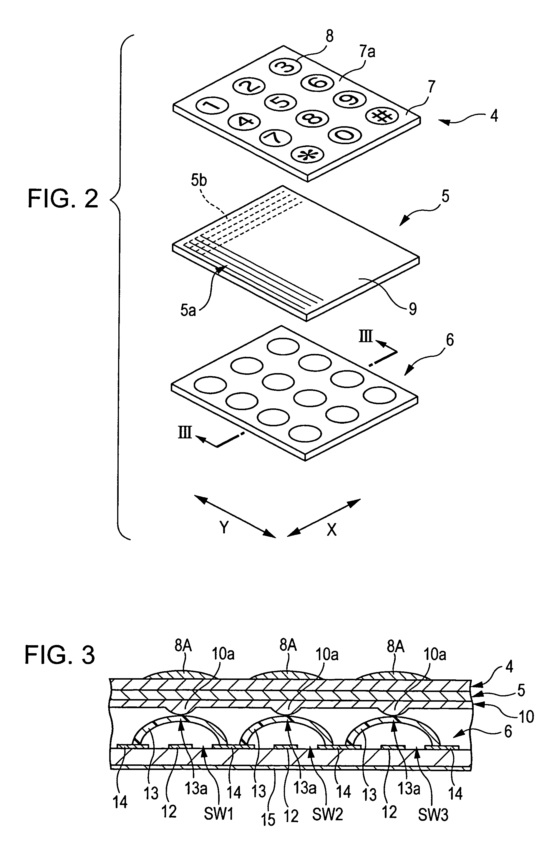
[0030]FIG. 1 is a partially perspective view of a portable telephone 1 having an input device according to the present invention, FIG. 2 is a partially exploded perspective view of the input device, FIG. 3 is a partially cross-sectional view of the input device shown in FIG. 2, taken along a line III-III, FIG. 4 is an electrical circuit diagram of a second input unit, FIG. 5 is a partially cross-sectional view of the input device shown in FIG. 3 that is pressed, FIG. 6 is an electrical circuit diagram of the second input unit when the input device shown in FIG. 3 is in a switch input mode, FIG. 7 is a block diagram of the input device, FIG. 8 is a flowchart showing a flow of processing from reception of coordinate data to detection of a switch position, and FIG. 9 is a diagram showing a coordinate data correcting operation according to the present invention.

[0031]The portable telephone 1 shown in FIG. 1 has a case 2 on which a display panel 3 serving as a display unit and an input d...


PUM


Abstract

An input device contains a plurality of push switch elements that are connected to a single switch signal line. When a switch signal is detected from the switch signal line, it is determined which push switch element is enabled based on coordinate data obtained from a primary input sensor. By using the coordinate data, only a single switch signal line is used to determine which push switch element is enabled.

Description

[0001]This application claims the benefit of priority to Japanese Patent Application No. 2004-152822 filed on May 24, 2004, herein incorporated by reference.BACKGROUND OF THE INVENTION[0002]1. Field of the Invention[0003]The present invention relates to an input device having primary input means serving as a coordinate input unit and secondary input means having a plurality of push switch elements.[0004]2. Description of the Related Art[0005]Japanese Unexamined Patent Application Publication No. 2002-123363 is directed to an input device for use in, for example, portable telephones. The input device disclosed in this publication includes an electrostatic-capacitance or pressure-sensitive flat input unit 4, a cover sheet 7 formed on a surface of the flat input unit 4, and switch elements 11 used for a switch input operation (see FIGS. 2 and 7 of the publication).[0006]In the above-noted publication, as recited in paragraph number [0022], the flat input unit 4 has a coordinate input c...

Claims


Application Information

Patent Timeline
Patent Type & Authority Patents(United States)
IPC IPC(8): G09G5/00G06F3/02G06F3/03G06F3/033G06F3/044
CPCG06F1/1626G06F1/1662G06F3/0202H04M1/23
Inventor SATO, TADAMITSU
Owner ALPS ALPINE CO LTD
Why Eureka
Try Eureka