
Color-coded method for tools

a tool and color-coding technology, applied in the field of tools, can solve the problems of visual obstruction of users' eyes, difficulty in locating tools,

Inactive Publication Date: 2011-03-01
CODEATOOL
View PDF7 Cites 25 Cited by
  • Summary
  • Abstract
  • Description
  • Claims
  • Application Information

AI Technical Summary

Benefits of technology

[0017]Because frequently nuts or bolts will fall from the wrenches or sockets while they are in use, the present invention provides an additional function: it allows the nuts and bolts of this invention to temporarily be secured into the wrenches or sockets so they are not easily dropped during installation and removal. This function would greatly aid many physically impaired persons, as well as persons with no impairments.
[0021]The present invention offers a multidimensional method of identification that will aid a multitude of persons. Because of its unique features, the present invention has several advantages that would aid first responders in an emergency situation under adverse conditions, such as rescue workers or persons in National Defense.

Problems solved by technology

The nuts and bolts often get dropped out of the wrenches or sockets and sometimes get lost during the installation or removal process.
Often the nuts or bolts that need to be removed by the user are visually obstructed or the work place is poorly lighted.
Much valuable time is lost sorting through the tools and fasteners just to determine the English from the metric system of measurement needed for a particular job.
More time is lost searching for specific sizes of a relatively small group of the more repeatedly used tools or fasteners, and still more time is lost recovering dropped or lost nuts and bolts.
Those inconveniences waste valuable time and can cause the user to become confused or frustrated, creating an uncomfortable work environment.

Method used


Image

  • Color-coded method for tools
  • Color-coded method for tools
  • Color-coded method for tools

Examples


Embodiment Construction

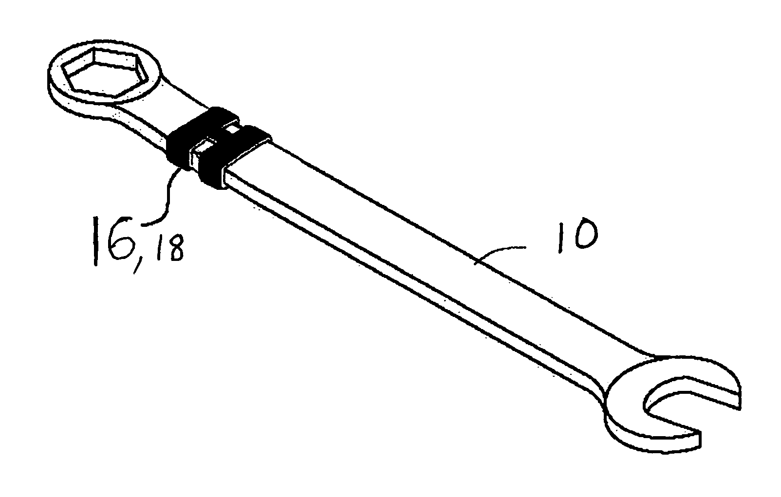
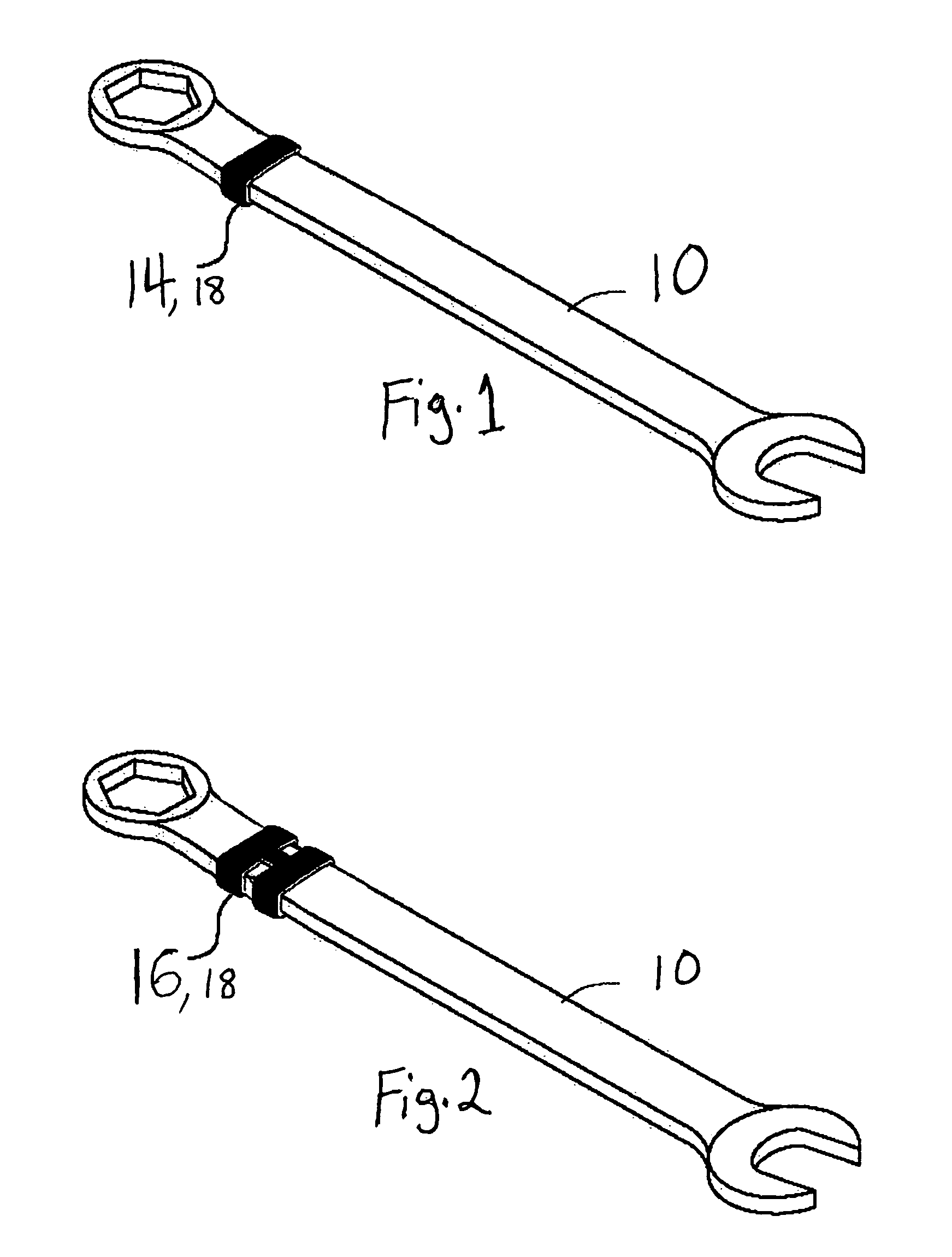
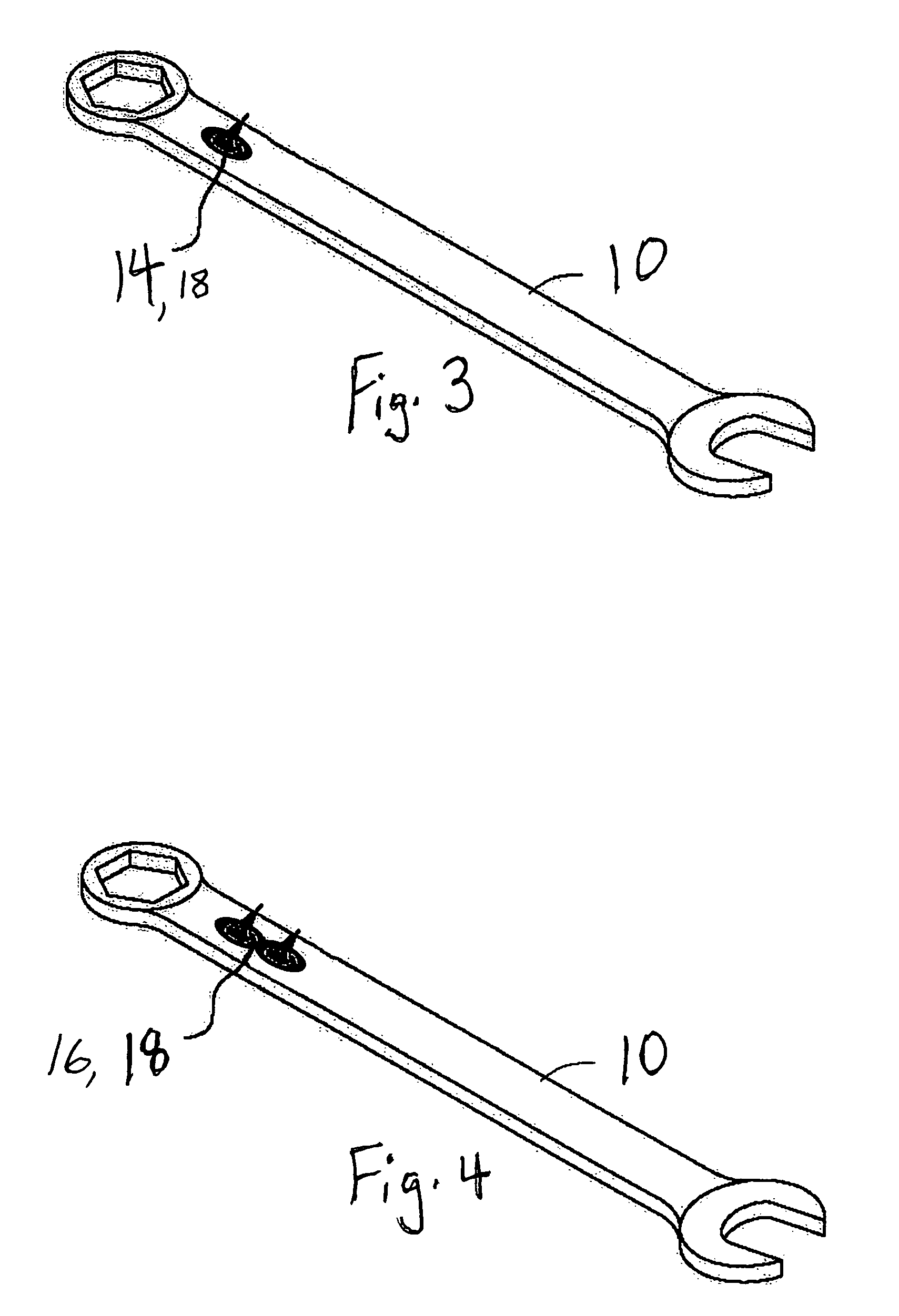
[0047]Turning now descriptively to the drawings, in which similar reference characters denote similar elements throughout the several views wherein FIGS. 1 through 10 illustrate the present invention wherein a method for identifying tools and sockets is discloses.

[0048]The tools and fasteners (wrenches, sockets, nuts and bolts) of the present invention provide a unique and easy to use multidimensional system of identification, that through natural human sensory perception, would allow visually impaired, or blind persons as well as non-visually impaired persons skilled in the art to instantly and easily distinguish the difference between the primary systems of measurement “English or metric” for the tools and fasteners they are working with. This primary coding system makes use of two of man's exterior senses, “sight and touch.” It may be used on all the sizes of English and metric tools and fasteners.

[0049]Some of the size differences between tools of the English and the metric syst...


PUM

PropertyMeasurementUnit
Sizeaaaaaaaaaa
Sizeaaaaaaaaaa
Sizeaaaaaaaaaa

Abstract

A method for identifying tools using the steps of providing a tool, wherein the tool is chosen from the group including a wrench, a socket, a nut, and a bolt; applying an indicator being a color-coded indicia onto the tool, wherein the indicia is visible to a user, wherein the indicia aids in identifying the tool, wherein the colors are chosen from the group including blue, red, orange, yellow, green, brown, violet and light gray; wherein the indicia is a band, the band being substantially flat, the band being raised an effective distance above the surface of the tool, wherein the band can be felt by a user, wherein the band aids in identifying the tool; and, wherein the band has a single portion, wherein the single portion can be felt by a user to identify English size tools. The method uses a band having two interconnected portions, wherein the two interconnected portions can be felt by a user to aid in identifying metric size tools. Also, the indicator may be a protrusion shaped like a tear-drop, an “X” or “O” shaped indicator, or an o-ring shaped indicator.

Description

RELATED APPLICATIONS[0001]This application is a Continuation-in-Part of U.S. patent application Ser. No. 10 / 830,883 filed Apr. 26, 2004, now abandoned by the Applicants.BACKGROUND OF THE INVENTION[0002]1. Field of the Invention[0003]The present invention relates generally to tools and, more particularly, is concerned with a method for identifying the size of tools.[0004]2. Description of the Prior Art[0005]Coding systems have been described in the prior art; however, none of the prior art devices disclose the unique features of the present invention.[0006]U.S. Pat. No. 4,982,627 to Johnson dated Jan. 8, 1991 disclosed color coded tools. U.S. Pat. No. 6,082,227 to Vogel dated Jul. 4, 2000 disclosed a visual coding system for tool size. U.S. Pat. No. 6,393,950 to Crosser dated May 28, 2002 disclosed color coded tools. U.S. Patent Application Publication US2004 / 0216566 to Shih dated Nov. 4, 2004 disclosed applying two pieces of tape to tools.[0007]In U.S. Pat. No. 6,082,227, dated Jul....

Claims


Application Information

Patent Timeline
IPC IPC(8): B23Q17/00
CPCB25B13/04B25B13/06B25B13/56B25B13/08Y10T29/49764Y10T29/49885
Inventor DUGAN, TIMOTHY W.
Owner CODEATOOL
Learn More