Method for driving liquid ejector

a liquid ejector and ejector technology, applied in piezoelectric/electrostrictive/magnetostrictive devices, piezoelectric/electrostriction/magnetostriction machines, printing, etc., can solve the problem of destabilizing the ejection of ink droplets from the nozzle, and reliably prevent the occurrence of noise vibration destabilizing ejection of ink droplets, and reduce the tensile stress applied to the inactive region

Active Publication Date: 2011-03-01
KYOCERA CORP
View PDF23 Cites 12 Cited by
  • Summary
  • Abstract
  • Description
  • Claims
  • Application Information

AI Technical Summary

Benefits of technology

[0045]In the invention according to Claim 1, the piezoelectric deformation region of the piezoelectric actuator is deflected in one thickness direction and the opposite direction individually and vibrated by applying the driving voltage waveform including the first voltage and the second voltage opposite in polarity to the first voltage and equivalent thereto. Therefore, in a unimorphic piezoelectric actuator, for example, the active region of the piezoelectric ceramic layer can be not only contracted in the plane direction and released from the contraction similarly to the conventional one but also expanded in the plane direction in ejection of an ink droplet and compressive stress can be applied to the inactive region surrounding the active region. As a result, the inactive region can be prevented from gradual creep deformation resulting in conventional one-sided expansion in the plane direction.
[0046]This also applies to other types of piezoelectric actuators. In a conventional bimorphic piezoelectric actuator, for example, an active region of a single piezoelectric ceramic layer (referred to as a first piezoelectric ceramic layer) must be continuously contracted in the plane direction while an active region of the other piezoelectric ceramic layer (referred to as a second piezoelectric ceramic layer) must be continuously expanded in the plane direction in a standby state. As a result, the respective inactive regions is gradually creep-deformed to be expanded in the plane direction in the first piezoelectric ceramic layer and to be contracted in the plane direction in the second piezoelectric ceramic layer.
[0047]According to the driving method of the invention in Claim 1, however, the active region of the first piezoelectric ceramic layer is expanded in the plane direction so that compressive stress can be applied to the inactive region surrounding the active region while the active region of the second piezoelectric ceramic layer is contracted in the plane direction so that tensile stress can be applied to the inactive region surrounding the active region. Thus, the inactive regions around the respective active regions can be prevented from gradual creep deformation.
[0048]In a conventional monomorphic piezoelectric actuator, on the other hand, an active region of a piezoelectric ceramic layer is continuously deflected in one layer thickness direction in a standby state. As a result, an inactive region is gradually creep-deformed so that an area of the inactive region in the thickness direction corresponding to the protruding side of the active region is compressed in the plane direction and an opposite area is expanded in the plane direction. In the driving method according to Claim 1 of the present invention, however, the piezoelectric ceramic layer is deflected also in the direction opposite to thickness direction so that tensile stress can be applied to the area of the inactive region in the thickness direction corresponding to the protruding side of the active region and compressive stress can be applied to an opposite area. Accordingly, the inactive region around the active region can be prevented from gradual creep deformation.
[0049]According to the driving method of the invention in Claim 1, the displacement of the deflected piezoelectric deformation region in the thickness direction with respect to a stationary state not subjected to voltage application can also be reduced as compared with the conventional one. Assuming that the displacement in the thickness direction between the stationary state and the deflected state is 1 in a conventional driving method deflecting the piezoelectric deformation region of the piezoelectric actuator only in one direction, for example, the displacements for deflecting the piezoelectric deformation region in one thickness direction and the opposite direction for setting the total displacement of the piezoelectric deformation region of the piezoelectric actuator in the thickness direction identically to 1 can be each generally halved in the driving method according to Claim 1 of the present invention. Therefore, the tensile stress applied to the inactive region of the piezoelectric ceramic layer can be reduced when the piezoelectric deformation region is deflected, whereby the inactive region can be further reliably prevented from gradual creep deformation.
[0050]According to the driving method of the invention in Claim 1, further, it is also possible to suppress occurrence of noise vibration destabilizing ejection of ink droplets caused in the conventional pull-push driving method in driving of the piezoelectric deformation region of the piezoelectric actuator. In other words, the displacement of the deflection of the piezoelectric deformation in the standby state can be reduced as compared with the conventional one in the driving method according to Claim 1 of the present invention as hereinabove described, whereby storage of elastic energy can be reduced.

Problems solved by technology

The vibration of this noise (noise vibration) is added to the aforementioned vibration of the ink resulting in a problem to destabilize the ejection of ink droplets from the nozzle 3.

Method used


Image

  • Method for driving liquid ejector
  • Method for driving liquid ejector
  • Method for driving liquid ejector

Examples


example 1

(Preparation of Piezoelectric Actuator)

[0156]Slurry was prepared by blending piezoelectric ceramic powder mainly composed of lead zirconate titanate having a particle diameter of 0.5 to 3.0 μm with an acrylic resin emulsion and pure water and mixing these materials with nylon balls having an average particle diameter of 10 mm in a ball mill for 30 hours. Then, the slurry was employed for forming a green sheet having a thickness of 17 to 19 μm for forming a piezoelectric ceramic layer 6 and a oscillator plate 12 on a polyethylene terephthalate (PET) film having a thickness of 30 μm by the pull-up method.

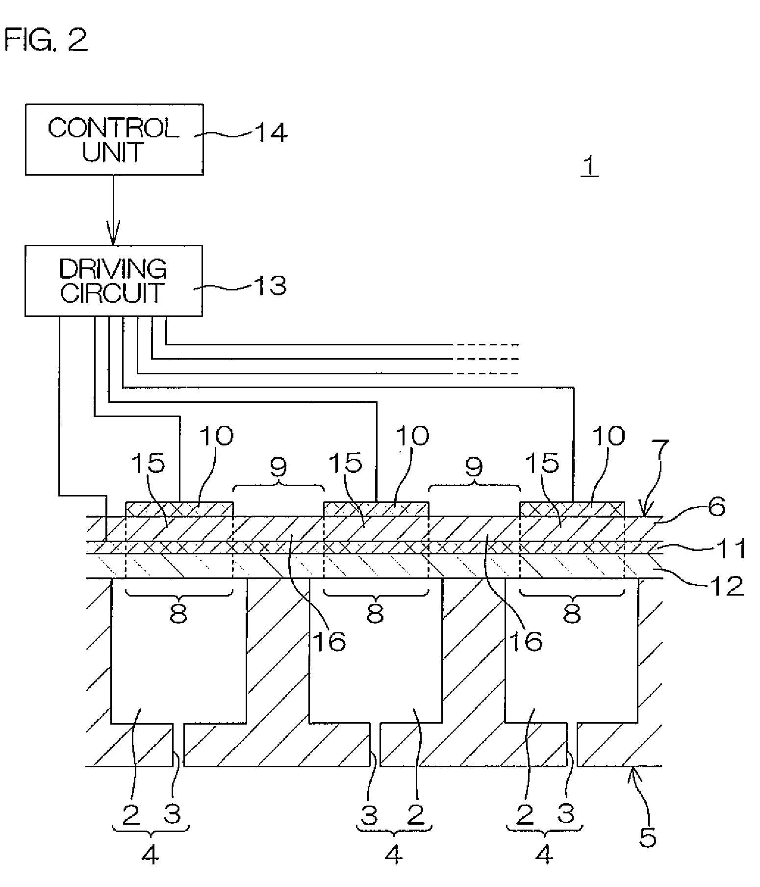
[0157]Then, the green sheet was cut into two squares of 50 mm by 50 mm along with the PET film was prepared, metal paste for forming a common electrode 11 was screen-printed generally on the entire exposed surface of one of the green sheet, and the two green sheets were thereafter dried in an explosion-proof drier at 50° C. for 20 minutes. As the metal paste, a powder was prepared by ...

example 2

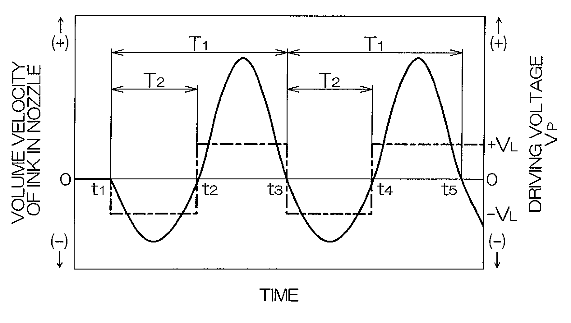
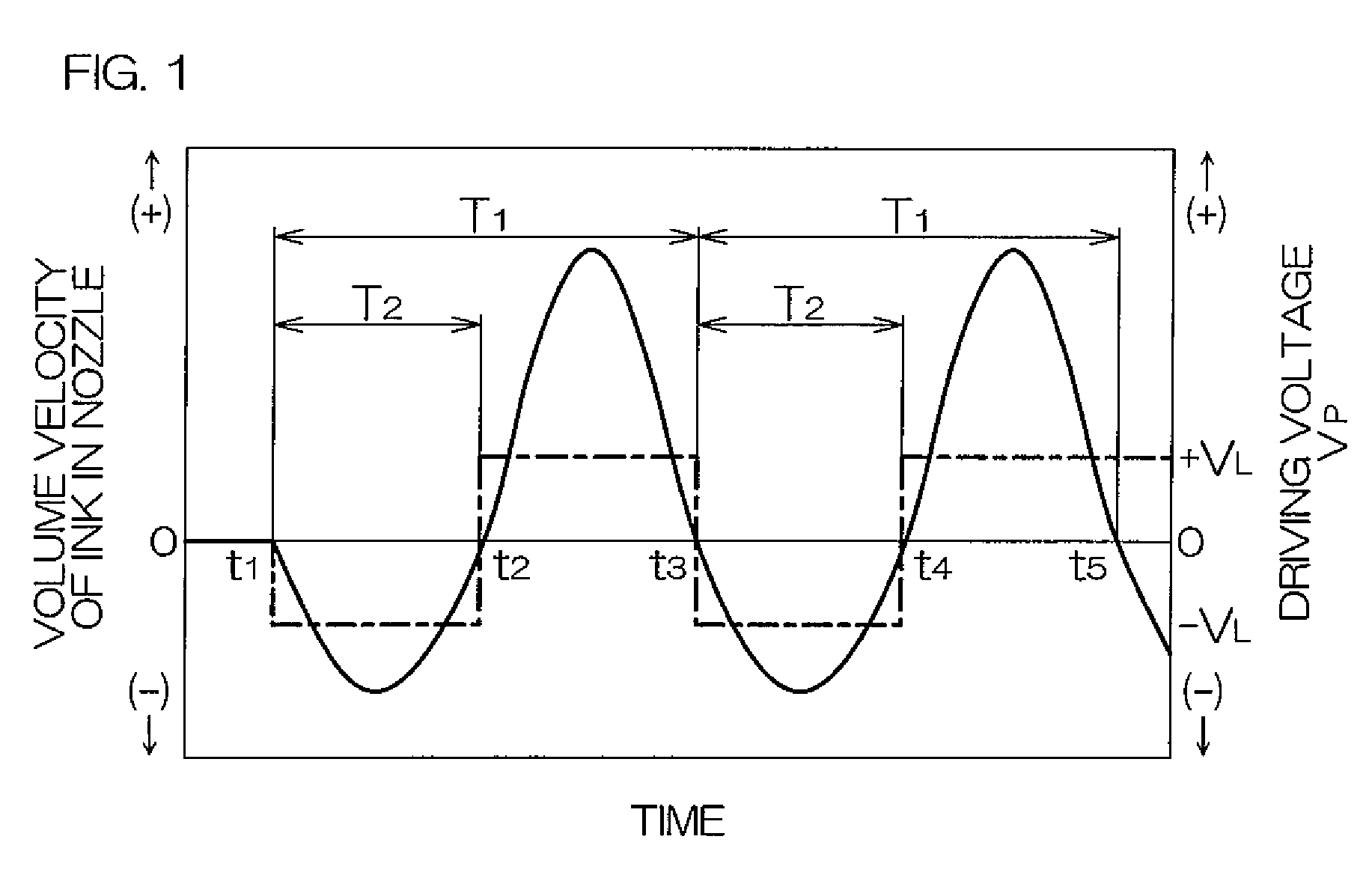
[0173]The liquid ejector 1 shown in FIG. 1 having a unimorphic piezoelectric actuator 7 was produced similarly to Example 1, except that the thickness of a piezoelectric ceramic layer 6 was set to 15 μm and a pressurizing chamber 2 was formed to have a plane shape of 2.2 mm by 0.65 mm. The coercive electric field Ec of the piezoelectric ceramic layer 6 was 17 kV / cm.

(Ejection Test)

[0174]When the driving voltage waveform (+VL=15 V, −VL=−15 V, driving frequency: 1 kHz) shown in FIG. 1 was applied to one piezoelectric deformation region 8 of the piezoelectric actuator 7 of the liquid ejector 1 produced according to Example 2 for driving the piezoelectric deformation region 8 by the driving method according to the present invention, so that a corresponding nozzle 3 ejected ink droplets under a condition of a head drop speed of 9 m / s. At the same time a strobe was flashed after 120 μs from the application of the driving voltage waveform for taking an image of ink droplets on a position of...


PUM


Abstract

A method for driving a liquid drop ejector (1) equipped with a piezoelectric actuator (7) including a piezoelectric ceramic layer (6) having a size covering a plurality of pressurizing chambers (2). An arbitrary piezoelectric deformation region (8) of the liquid drop ejector (1) is deflected in one thickness direction and the opposite direction, respectively, by applying a driving voltage waveform including a first voltage (−VL) and an equivalent second voltage (+VL) of the opposite polarity in order to vary the volume of the pressurizing chambers (2) of a corresponding liquid drop ejecting portion (4), and a liquid drop is ejected through a communicating nozzle (3). Since gradual creep deformation of the inactive region (16) of the piezoelectric ceramic layer (6) is prevented, the ink drop ejection performance is maintained at a good level over a long term.

Description

CROSS-REFERENCE TO THE RELATED APPLICATIONS[0001]This application is a national stage of the international application No. PCT / JP2006 / 312622 filed Jun. 23, 2006, which also claims benefit of priority under 35 U.S.C. §119 to Japanese Patent Application No. 2005-185791 filed Jun. 24, 2005and Japanese Patent Application No. 2005-376131 filed Dec. 27, 2005, the entire contents of both of which are incorporate herein by reference.TECHNICAL FIELD[0002]The present invention relates to a method for driving a liquid ejector.PRIOR ART[0003]FIG. 2 is a sectional view showing an example of a liquid ejector 1 employed for an on-demand ink jet printer or the like. FIG. 3 is a sectional view showing a principal part of the example of the liquid ejector 1 in an enlarged manner. Referring to FIGS. 2 and 3, the liquid ejector 1 of this example includes a substrate 5 formed by arranging a plurality of liquid droplet ejecting portions 4 having pressurizing chambers 2 to be filled with ink and nozzles 3...

Claims


Application Information

Patent Timeline
Patent Type & Authority Patents(United States)
IPC IPC(8): B41J29/38H02N2/00H01L41/00B41J2/045
CPCB41J2/04525B41J2/04581B41J2/04588B41J2/14233B41J2002/14266
Inventor IWASHITA, SHUZOISHIKURA, SINYAMAMOTO, TAKAYUKISAKAI, HISAMITSU
Owner KYOCERA CORP
Why Eureka
Try Eureka