
Method to produce conductive transfer roller, transfer roller, and image forming apparatus having the same

a technology of transfer rollers and forming apparatuses, which is applied in the direction of manufacturing tools, portable power-driven tools, instruments, etc., can solve the problems of severe resistance change, difficult to achieve uniform electronic conductivity, and difficult to regulate the amount of carbon, etc., to achieve stable and uniform foam structure

Inactive Publication Date: 2011-03-01
HEWLETT PACKARD DEV CO LP
View PDF24 Cites 6 Cited by
  • Summary
  • Abstract
  • Description
  • Claims
  • Application Information

AI Technical Summary

Benefits of technology

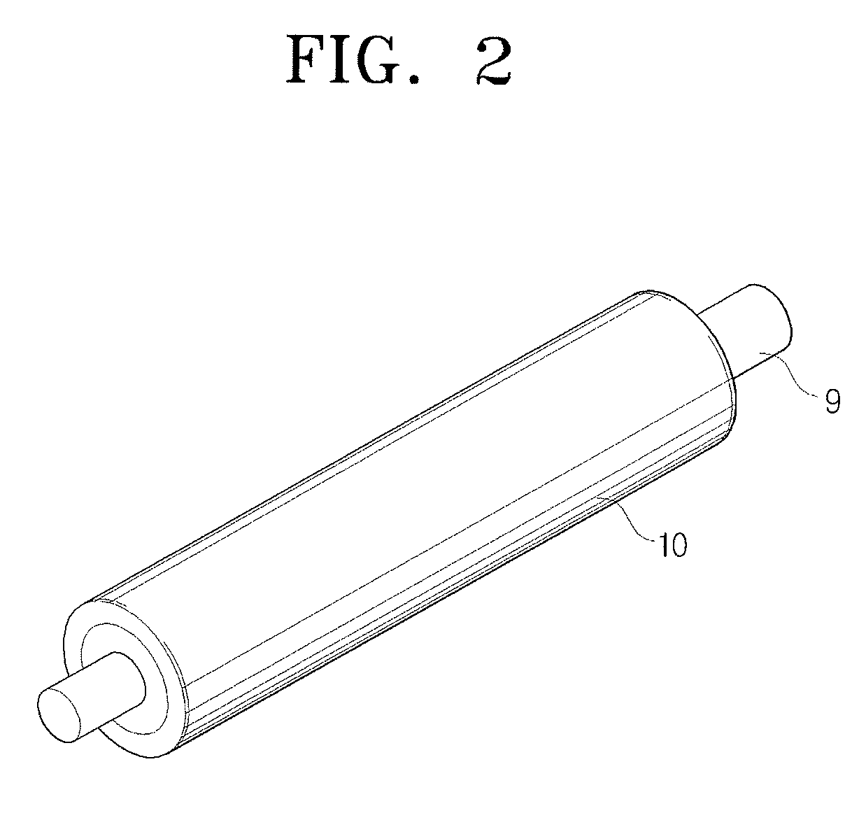
[0011]The present general inventive concept provides an improved method to produce a conductive transfer roller of an ionic conductive type and an electron conductive type using a continuous mobile foaming method to apply the conductivity. The conductive transfer roller of the present general inventive concept achieves a stable and uniform foam structure by applying the continuous mobile foaming method.

Problems solved by technology

However, it is quite hard to regulate the amount of carbon to adjust the resistance in the production.
The non-uniform electric resistance makes it hard to acquire the uniform electronic conductivity.
However, its severe resistance change according to the environment requires high voltage.
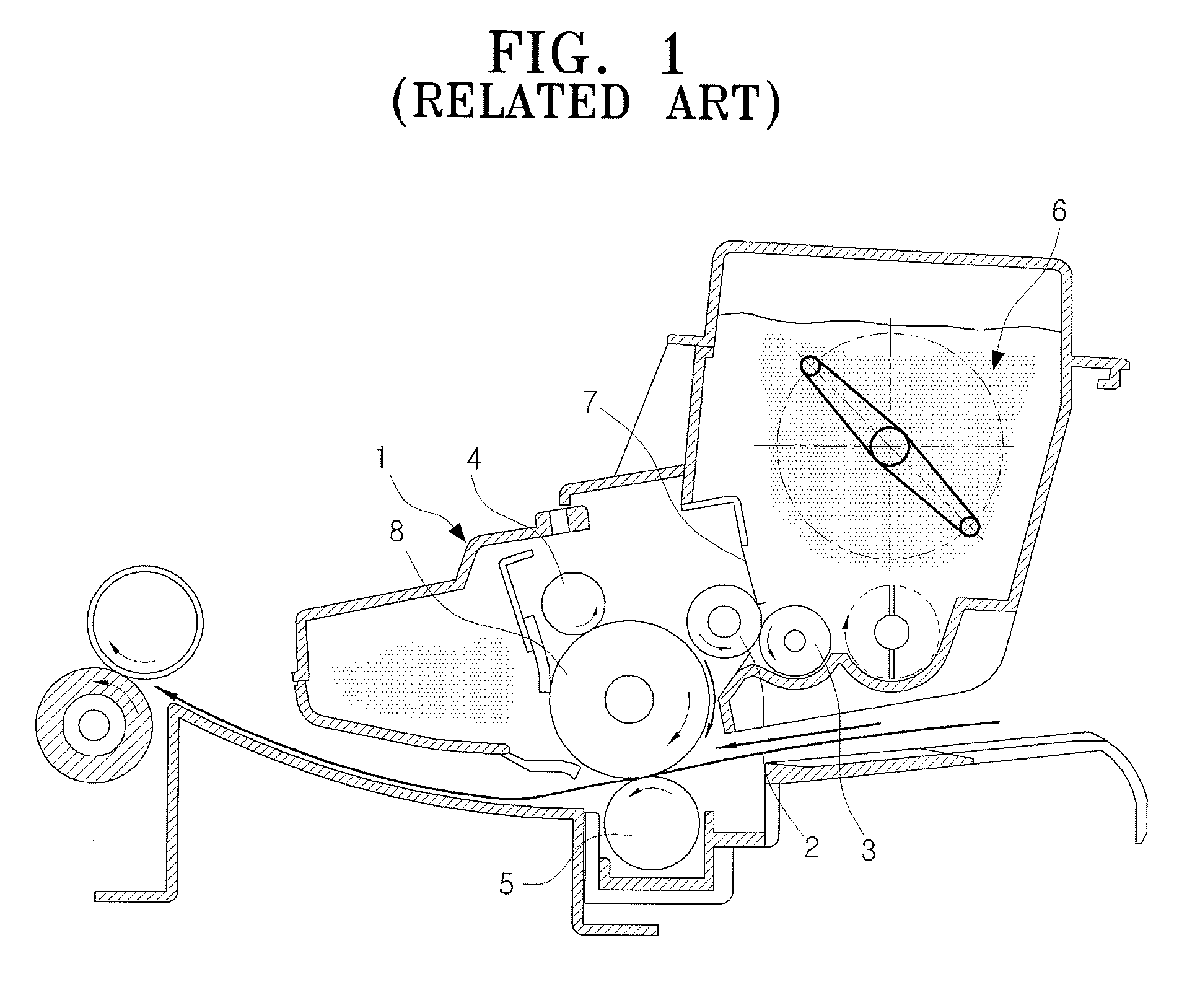
The photoconductive drum 8 may be contaminated because of the leakage of a charging control material added in the production of the conventional transfer roller 5.
However, it is hard to transfer the uniform heat to the rubber material and to acquire the uniform foam in the mold forming vulcanization or the hot wind vulcanization.

Method used


Image

  • Method to produce conductive transfer roller, transfer roller, and image forming apparatus having the same
  • Method to produce conductive transfer roller, transfer roller, and image forming apparatus having the same
  • Method to produce conductive transfer roller, transfer roller, and image forming apparatus having the same

Examples


examples

Ingredients were Mixed According to the Ratios of Table 1 and Test Samples were Produced

[0053]

TABLE 1SubstanceExample 1Example 2Example 3Comparison 1Comparison 2NBR8080808080ECO2020202020calcium carbonate2020202020carbon black1098.5105.5sulfur1.51.51.51.51.5conductive carbon11.21.5—4.5blackionic conductive0.50.30.22.5—agentstearic acid11111zinc oxide55555blowing agent44444(ADCA)urea11111anti-aging agent0.50.50.50.50.5vulcanization11111acceleratorfoaming methodcontinuouscontinuouscontinuousvulcanizingvulcanizingfoamingfoamingfoamingpipe foamingpipe foamingadhesivesnonenonenoneapplyapplyadhesivesadhesives

[0054]Using the samples produced according to Examples 1, 2 and 3 using the present general inventive concept and according to Comparisons 1 and 2 using a conventional process, the drum contamination, the hardness, the electrical resistance, the foaming shape, and the uniformity were assessed as illustrated in Table 2.

[0055]Drum contamination assessment: the transfer roller 10 was put...


PUM

PropertyMeasurementUnit
temperatureaaaaaaaaaa
lengthaaaaaaaaaa

Abstract

A method to produce a conductive transfer roller, and the transfer roller. The method to produce the conductive transfer roller includes adding and mixing a conductive substance, an ionic conductive agent, a vulcanizing agent, and a blowing agent and at least one of elastic materials selected from a group consisting of EPMD (ethylene propylene) rubber, NBR (acrylonitrile butadiene) rubber, ECO (epichlorohydrin ethylene oxide) rubber, and CR (chloroprene rubber), extruding the compound, blowing the extruded material by passing it through a continuous mobile foaming device, pressing the foam onto a shaft and applying a secondary curing, and grinding the foam to a desired thickness.

Description

CROSS-REFERENCE TO RELATED APPLICATIONS[0001]This application claims the benefit under 35 U.S.C. §119 (a) from Korean Patent Application No. 10-2007-0066247, filed on Jul. 2, 2007, in the Korean Intellectual Property Office, the entire disclosure of which is incorporated herein by reference in its entirety.BACKGROUND OF THE INVENTION[0002]1. Field of the Invention[0003]The present general inventive concept relates generally to a method to produce a transfer roller used in an image forming apparatus and the transfer roller. More particularly, the present general inventive concept relates to a method to produce a conductive transfer roller by passing through a continuous mobile oven foaming device. The produced conductive transfer roller is applicable to image forming apparatuses using electro photography, such as printers, copiers, and fax machines.[0004]2. Description of the Related Art[0005]FIG. 1 illustrates a conventional image forming apparatus 1. The image forming apparatus 1 i...

Claims


Application Information

Patent Timeline
Patent Type & Authority Patents(United States)
IPC IPC(8): B25F5/02B29C44/00G03G15/01G03G5/00G03G15/14B29C48/465
CPCB29C44/32G03G15/1685C08J9/0014B29C47/522C08J2201/03C08J2311/00C08J2321/00C08J2323/16C08J2309/02B29K2009/00B29K2019/00B29K2995/0005B29K2011/00B29C44/26B29C44/3415B29C44/5627B29C44/507B29C48/465G03G15/14
Inventor JI, YOUNG-PHIL
Owner HEWLETT PACKARD DEV CO LP
Learn More