Electric drive

a technology of electric drive and drive shaft, which is applied in the direction of vehicle maintenance, vehicle cleaning, transportation and packaging, etc., can solve the problems of complex design of electric drive, and achieve the effects of reducing tool costs, reducing tool costs, and producing very reliably

Inactive Publication Date: 2011-03-01
ROBERT BOSCH GMBH
View PDF7 Cites 32 Cited by
  • Summary
  • Abstract
  • Description
  • Claims
  • Application Information

AI Technical Summary

Benefits of technology

[0002]The electric drive according to the invention has the advantage over the above that the variety of tools and the tool costs can be considerably reduced by using an identical assembly comprising a brush holder mount and an interference suppression module for different gear mechanism positions.
[0003]It is particularly expedient here when the retaining means on the interference suppression module and on the brush holder mount are designed as a groove and tongue connection because the interaction of such retaining means can be produced very reliably and at the same time easily, as a result of which the tool costs can be substantially reduced. In this case, identical tongue projections are preferably formed on opposite sides of a cutout in the brush holder mount and grooves, which are arranged with mirror-image symmetry to said cutout, are arranged on the interference suppression module because guide ribs which run on the brush holder mount can be easily integrally formed and then only associated groove-like notched areas have to be provided on the interference suppression module which is in the form of an insert part.

Problems solved by technology

Such a design of the electric drive is complex, in particular with regard to the variety of tools required and the resultant tool costs.

Method used


Image

  • Electric drive
  • Electric drive
  • Electric drive

Examples


Embodiment Construction

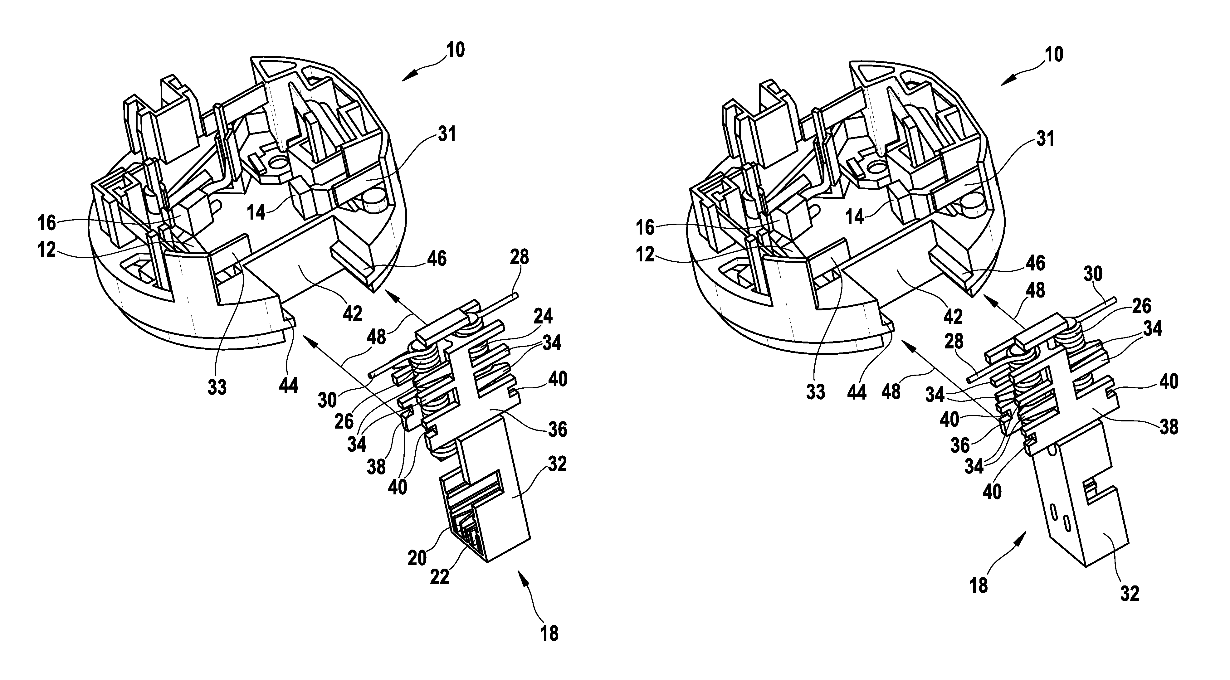
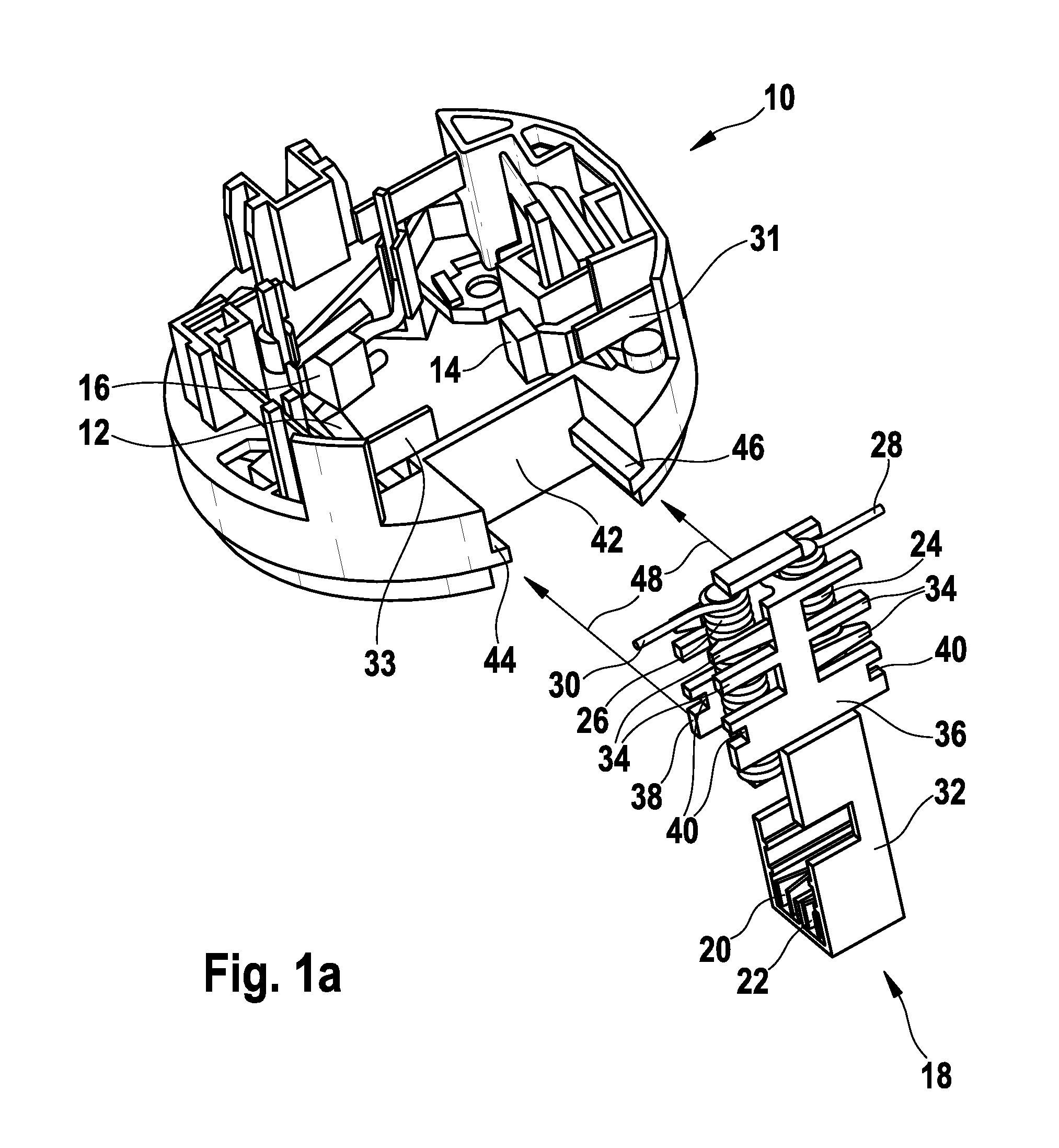
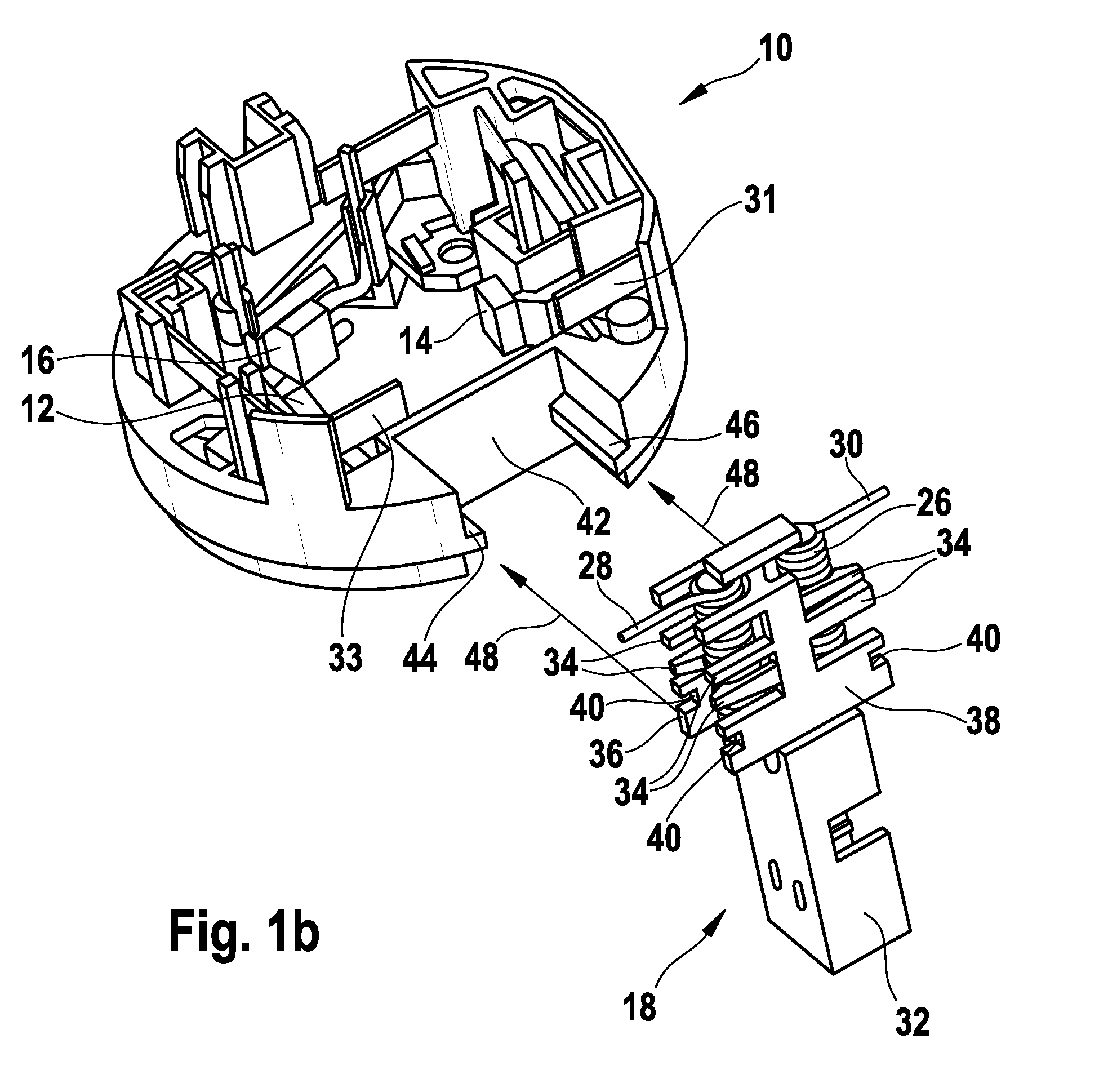
[0009]In FIGS. 1a and 1b, 10 denotes a brush holder mount for an electric drive motor of a windshield wiper system; the entire arrangement of the drive is explained in greater detail below with reference to FIGS. 2a and 2b.

[0010]Brushes 12, 14 and 16 are held in the brush holder mount, with the opposite brushes 12 and 14 feeding the motor at a relatively low rotational speed and the brushes 14 and 16 feeding the motor at a relatively high rotational speed. Two identical interference suppression modules 18, which are mechanically and electrically connected to the brush holder mount 10 for electrical connection and for radio interference suppression of the motor, are illustrated beneath the brush holder mount 10. For different gear mechanism positions of the electric drive, the structurally identical interference suppression module can, in this case, be mounted on the brush holder mount 10 in two installation positions which are rotated through 180°, so that the same interference sup...


PUM


Abstract

An electric drive, in particular a wiper drive for vehicles, is proposed, with an electric driving motor in a motor housing (50), a brush holder (10) projecting into the motor housing (50), an anti-interference module (18) which is connected electrically and mechanically to the brush holder (10) and is intended for the electrical connection and interference protection of the motor, and with a gear mechanism (52) which is attached to the motor housing (50), at least partially accommodates the anti-interference module (18) and is designed in accordance with the predetermined position of the output shaft (53) with respect to the drive shaft (58). According to the invention, the diversity of components of the electric drive and therefore, in particular, the diversity of tools for producing the components are reduced by the anti-interference module (18) and the brush holder (10) being equipped with corresponding retaining means (40, 44) which permit the installation of a structurally identical anti-interference module (18) on the brush holder (10) in two installation positions rotated through 180°.

Description

BACKGROUND AND SUMMARY OF THE INVENTION[0001]The invention is based on an electric as known, for example, from DE 39 30 144 A1. Said document discloses a small electric motor for driving windshield wipers in motor vehicles, which motor has an interference suppression module arranged in a pocket of the gear mechanism pot, said interference suppression module at the same time performing the function of an electrical connection part from the brushes of the electric motor to the external connections. In this case, the brush arrangement of the motor is seated on a plate which is fitted with the interference suppression module which projects into the gear mechanism housing and, for its part, has to be designed in accordance with the structure and the orientation of the gear mechanism housing in each case individually. Such a design of the electric drive is complex, in particular with regard to the variety of tools required and the resultant tool costs.[0002]The electric drive according to...

Claims


Application Information

Patent Timeline
Patent Type & Authority Patents(United States)
IPC IPC(8): H02K13/00
CPCB60S1/08B60S1/166H02K11/026H02K5/225H02K7/1166H02K5/148H02K11/02H02K7/116
Inventor HURST, RICHARDHEYDER, MARTINKOESTERS, MATTHIASMARTIN, NORBERT
Owner ROBERT BOSCH GMBH
Why Eureka
Try Eureka