Torque controller in an electric motor

a torque controller and electric motor technology, applied in the direction of dynamo-electric machines, dc motor speed/torque control, ac commutator, etc., can solve the problems of limiting the stall torque, reducing the torque at stall, and limiting the heat dissipation of the igb

Active Publication Date: 2011-03-01
DRS NETWORK & IMAGING SYST
View PDF8 Cites 800 Cited by
  • Summary
  • Abstract
  • Description
  • Claims
  • Application Information

AI Technical Summary

Problems solved by technology

The IGBTs are limited in the amount of heat they can dissipate.
Therefore, under the same switching conditions, the two switches cannot deliver the same amount of current to the motor at stall as the six switches can provide during rotation, thus limiting the stall torque.
However, because the current is reduced, the torque at stall is reduced, and the full operational range is handicapped based on the nature of the stall condition.
Torque pulsations may cause damage to mechanical components.

Method used


Image

  • Torque controller in an electric motor
  • Torque controller in an electric motor
  • Torque controller in an electric motor

Examples


Embodiment Construction

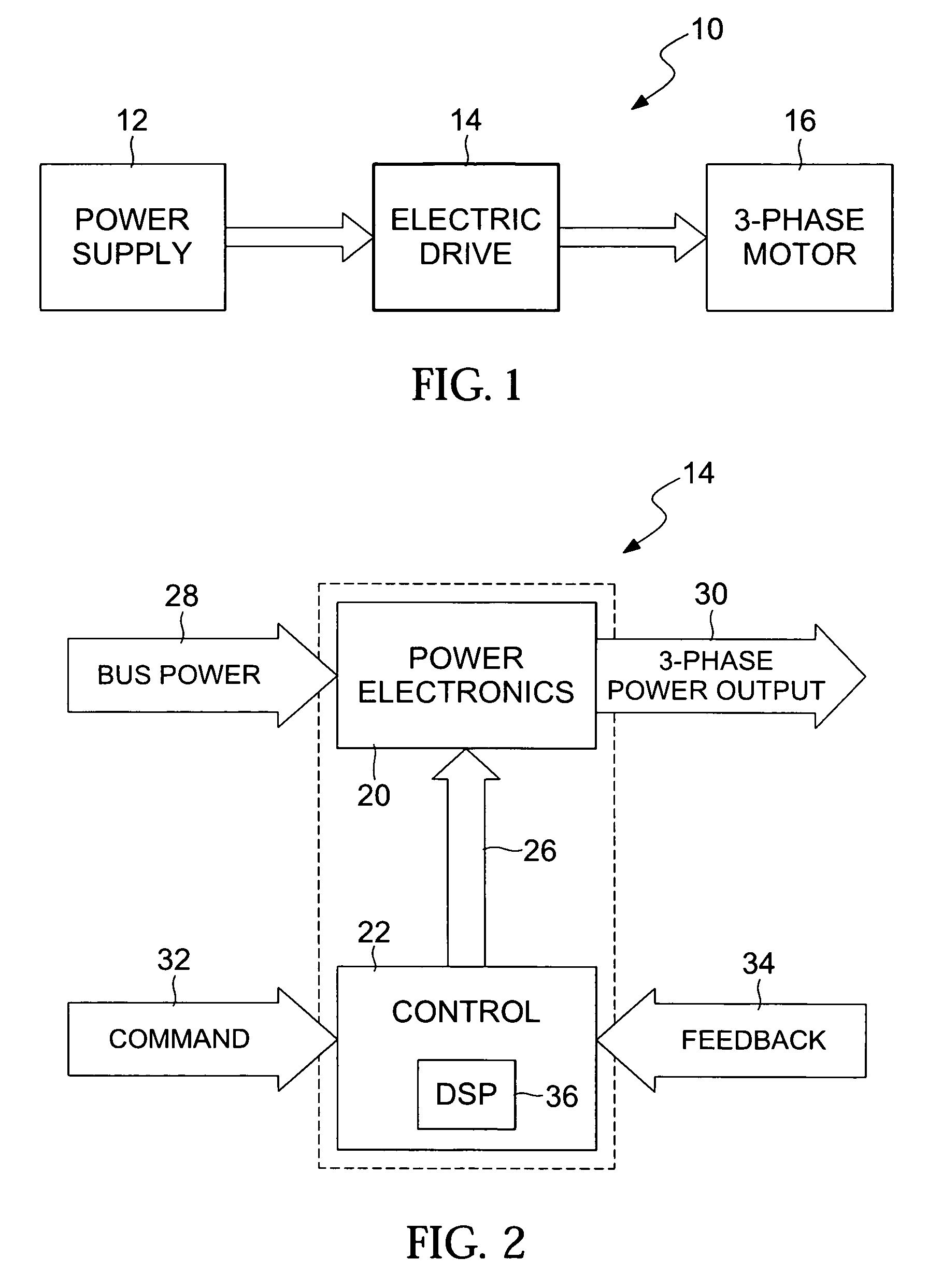
[0014]Referring to the drawings for a better understanding of the function and structure of the invention, FIG. 1 shows a block diagram of a motor system 10. The motor system 10 includes a power supply 12, an electric drive 14, and a 3-phase motor 16. The power supply 12 provides power to the motor 16. The power supply is preferably a direct current power source. An AC source with a rectifier may also be used to provide power to the electric drive 14. The electric drive 14 controls the power from the power supply 12 to the 3-phase motor 16. As further described below, the electric drive 14 modulates the power and provides the power according to the control design of the electric drive 14 to the 3-phase motor 16. In this manner, the electric drive 14 may control variables such as the speed and torque of the 3-phase motor 16. The electric drive 14 may also receive speed and torque feedback from the 3-phase motor 16 and also receive speed and torque input from a user wishing to control...


PUM


Abstract

The torque of a motor operated by an inverter circuit is controlled to allow maximum torque in the motor when the motor is stalled or at low rotation speeds. Control is accomplished by providing a switching frequency to the motor at a first switching frequency, detecting a rotation speed of the motor, and switching the current to the motor to a second switching frequency when the rotation speed of the motor drops to a predetermined slow rotation speed. The second switching frequency is less than the first switching frequency.

Description

[0001]This application claims the benefit of filing priority under 35 U.S.C. §119 and 37 C.F.R. §1.78 of the U.S. Provisional Application Ser. No. 60 / 695,226 filed Jun. 29, 2005, for a Stall Torque Controller. All information disclosed in the prior pending provisional application is incorporated herein by reference.FIELD OF THE INVENTION[0002]The present invention relates generally to electric motors controlled by power electronics. More particularly, the present invention relates to a pulse width modulated controller and a method of controlling an electric motor.BACKGROUND OF THE INVENTION[0003]Electric motors may be controlled by a group of insulated gate bipolar transistors (IGBTs). The IGBTs regulate the flow of current to the stator. The stator is composed of stationary windings in the motor which generate a magnetic field when excited. Current flows through the IGBTs when the IGBTs close (i.e., form a closed circuit), which allows current to flow through the stator windings. T...

Claims


Application Information

Patent Timeline
Patent Type & Authority Patents(United States)
IPC IPC(8): H02P7/00
CPCH02P23/03
Inventor MURPHREE, JERRY EONY
Owner DRS NETWORK & IMAGING SYST
Why Eureka
Try Eureka