Removable shutter for a camera

a shutter and camera technology, applied in the field of camera components, can solve the problems of system downtime, costly and time-consuming to be prevented from operating an airborne system, and curtailed planned activity, so as to reduce the downtime caused by component repair or replacement, reduce the downtime of lens systems and shutter systems, and reduce the effect of downtim

Active Publication Date: 2011-03-01
TELEDYNE DIGITAL IMAGING INC
View PDF10 Cites 35 Cited by
  • Summary
  • Abstract
  • Description
  • Claims
  • Application Information

AI Technical Summary

Benefits of technology

[0012]An additional object of the invention is make available a camera in which a variety of different lens systems may be interchanged for use without the necessity of recalibration or realignment of the components of the camera.
[0013]A further object of the invention is to provide a photographic imaging system configured to reduce downtime caused by component repair or replacement.
[0014]A still further object of the invention is provide a photographic imaging system constituted to enable relatively rapid replacement of lens systems and shutter systems during operation of the system.

Problems solved by technology

One problem that exists with such camera systems is system downtime.
It is costly and time consuming to be prevented from operating an airborne system because one component malfunctions.
This is especially true if a malfunction occurs while the system is in the air.
Not only is the planned activity curtailed, but the operating and personnel costs are increased due to the necessity to repeat the curtailed operation(s).
Moreover, equipment repair often necessitates disassembly, shipment to the OEM (original equipment manufacturer) for repair, and recalibration once a new or repaired component is finally made available to the system operator.
One especially vulnerable component is the camera shutter used in aerial photography systems.
Because these elements are subjected to rapid and repeated movement, they tend to wear down over time leading to shutter failure.
Such failure often occurs in mid-operation as there is ordinarily no method of determining beforehand when shutter components are about to fail.
This leads not only to a waste of time and resources caused by prematurely discontinuing an operation, but also extends downtime originating from removing the camera, shipping it to the OEM or a repair center, shipping the repaired camera back, and calibrating the camera to the whole system.

Method used


Image

  • Removable shutter for a camera
  • Removable shutter for a camera
  • Removable shutter for a camera

Examples


Embodiment Construction

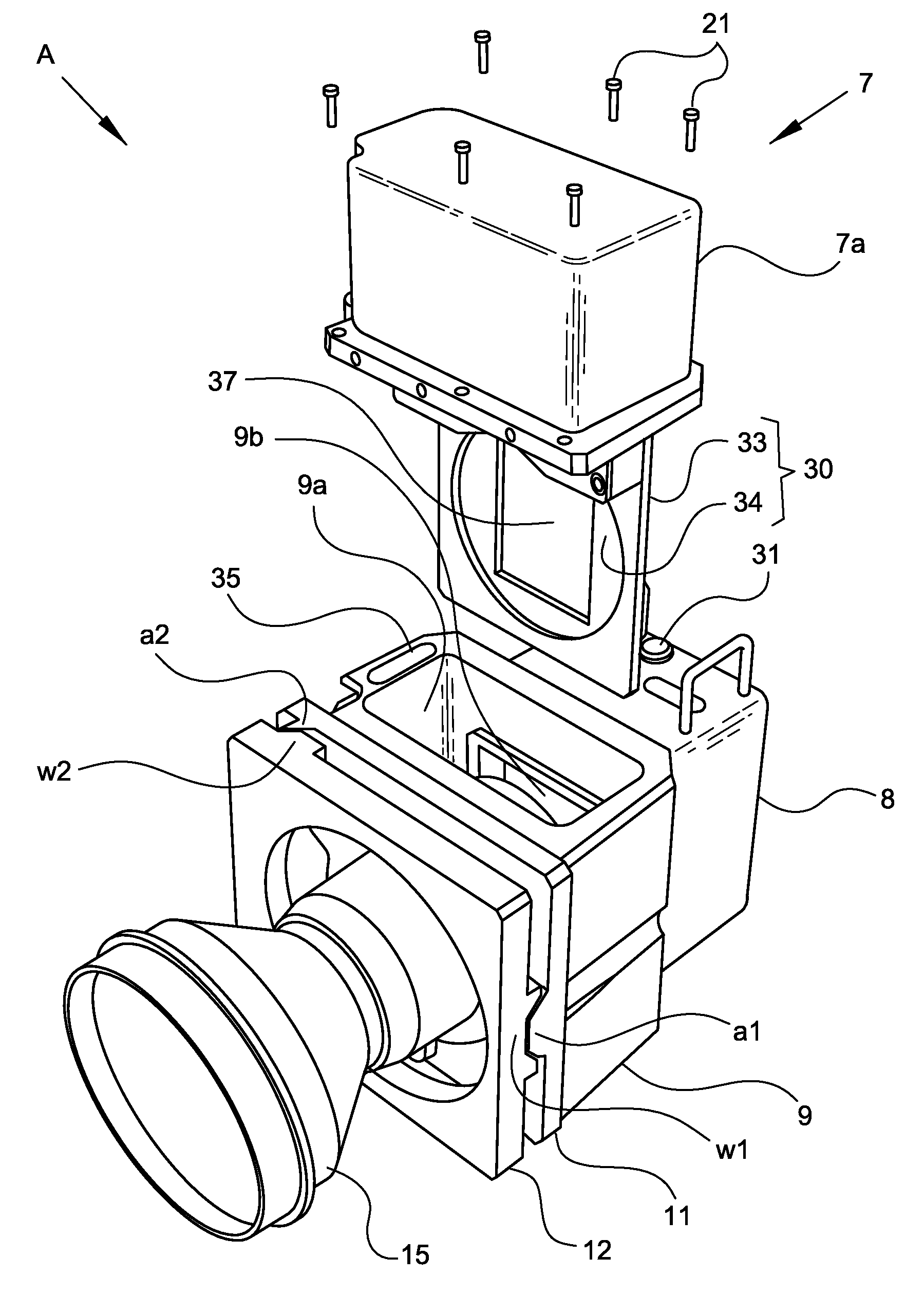
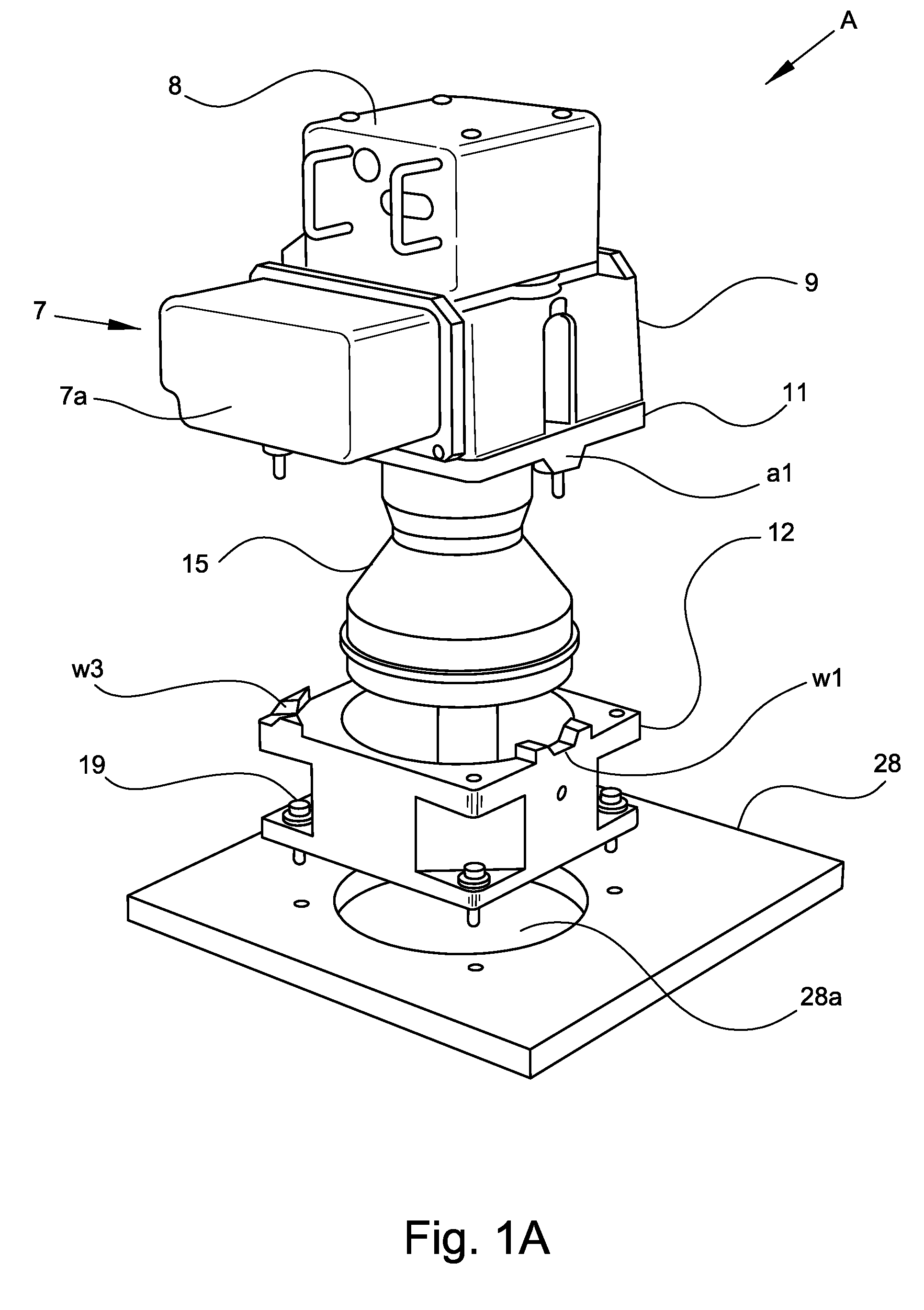
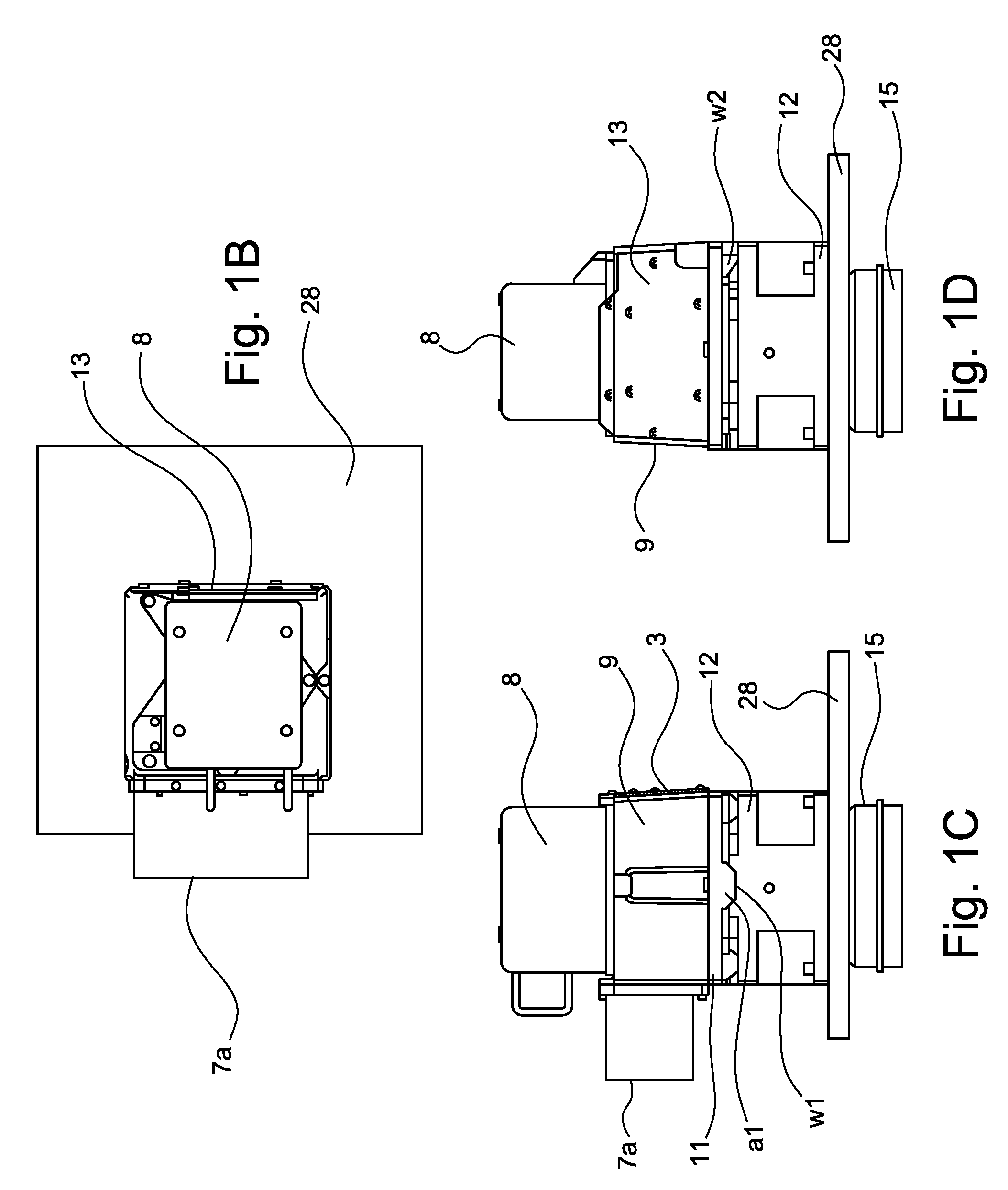
[0029]At the outset, it should be appreciated that like drawing numbers on different drawing views identify identical structural elements of the invention. It also should be appreciated that figure proportions and angles are not always to scale in order to clearly portray the attributes of the present invention.

[0030]While the present invention is described with respect to what is presently considered to be the preferred embodiments, it is understood that the invention is not limited to the disclosed embodiments. The present invention is intended to cover various modifications and equivalent arrangements included within the spirit and scope of the appended claims.

[0031]Furthermore, it is understood that this invention is not limited to the particular methodology, materials and modifications described and as such may, of course, vary. It is also understood that the terminology used herein is for the purpose of describing particular aspects only, and is not intended to limit the scope...


PUM


Abstract

The present invention is a camera system having a rigid camera frame to receive a removable shutter and serve as a releasable attachment point for the camera lens system and image receiving means. An adaptor and wedge have complementary contact points that allow constant alignment and orientation of the system components after removal and reattachment without recalibration or realignment. The camera system may be used in a photographic imaging system such as an airborne reconnaissance system.

Description

CROSS-REFERENCE TO RELATED APPLICATIONS[0001]The present application claims benefit under 35 U.S.C. §119(e) of U.S. Provisional Patent Application Ser. No. 61 / 125,867 filed Apr. 29, 2008.FIELD OF THE INVENTION[0002]The present invention pertains to components for a camera, including a camera shutter, specifically a replaceable camera shutter and other components assembled so as to reduce or eliminate the need for repeated recalibration or realignment when camera components are removed and replaced.BACKGROUND OF THE INVENTION[0003]The use of airborne camera systems is known in the art. Such systems are used for aerial mapping, monitoring of natural resources, reconnaissance, and other activities. Although some of these systems are used in orbiting satellites, they are also used in airplanes that are especially equipped with stable rack arrangements to hold the cameras to obtain images that are as clear and detailed as possible.[0004]One problem that exists with such camera systems is...

Claims


Application Information

Patent Timeline
Patent Type & Authority Patents(United States)
IPC IPC(8): G03B9/08
CPCG03B9/08G03B37/04
Inventor KEARNEY, KEVIN J.HAMMOND, PETERMARINO, PHILIP FRANK
Owner TELEDYNE DIGITAL IMAGING INC
Why Eureka
Try Eureka