Closed forging die and forging method

a forging die and closed technology, applied in the direction of manufacturing tools, forging/hammering/pressing machines, mechanical equipment, etc., can solve the problems of die damage or short-lived, drastically increase the processing load, etc., to reduce material costs and machining costs, and facilitate flow

Active Publication Date: 2011-03-08
NTN CORP
View PDF17 Cites 4 Cited by
  • Summary
  • Abstract
  • Description
  • Claims
  • Application Information

AI Technical Summary

Benefits of technology

[0011]In view of the above problems, it is an object of the present invention to provide a closed forging die and a forging method with which sagging can be reduced, which can make a constant velocity joint or a universal joint compact and lightweight, which do not require a shaft tip to be removed by machining prior to heat treatment, and which can reduce material costs and machining costs.
[0015]According to the forging method of the present invention, in the material to be introduced in the closed forging die, the radius of curvature of the surface, which is to be molded into the tip surface of each of the shaft portions, is larger than the radius of curvature of the tip surface of each of the shaft portions to be molded. Thus, in the process of molding the product configuration using the closed forging die (referred to as principal molding), even when the peripheral portion of the tip surface of the shaft portion less easily flows than the center portion thereof, “sagging” (an amount by which a circumferential surface side is retracted toward a base end portion side of the shaft portion in an axial direction thereof) can be reduced. In other words, prior to the principal molding, there is performed a preliminary molding process of molding the material such that the radius of curvature of the portion to be molded into the tip surface of each of the shaft portions is larger than the radius of curvature of the tip surface of each of the shaft portions to be molded. In the case of molding by using the closed forging die a product from the material which has been subjected to the preliminary molding process, even though a clearance is formed in the closed forging die, the “sagging” in the shaft portion can be reduced.
[0016]In the closed forging die according to the present invention, since the portion secured by the dies can be used as a referential surface for phase matching in the case of the highly-accurate machining, the shaft tip is not necessarily to be removed by machining in order to form a referential surface (referential portion) prior to heat treatment, to thereby reduce material costs and machining costs.
[0017]According to the present invention, the “sagging” can be reduced in the shaft portion, and thus a constant velocity joint or a universal joint employing the forged product can be made compact and lightweight.

Problems solved by technology

Incidentally, in a case where a sealed state is established in the closed forging die, a processing load drastically increases, which leads to a fear in that the die may be damaged or short-lived.

Method used


Image

  • Closed forging die and forging method
  • Closed forging die and forging method
  • Closed forging die and forging method

Examples


example

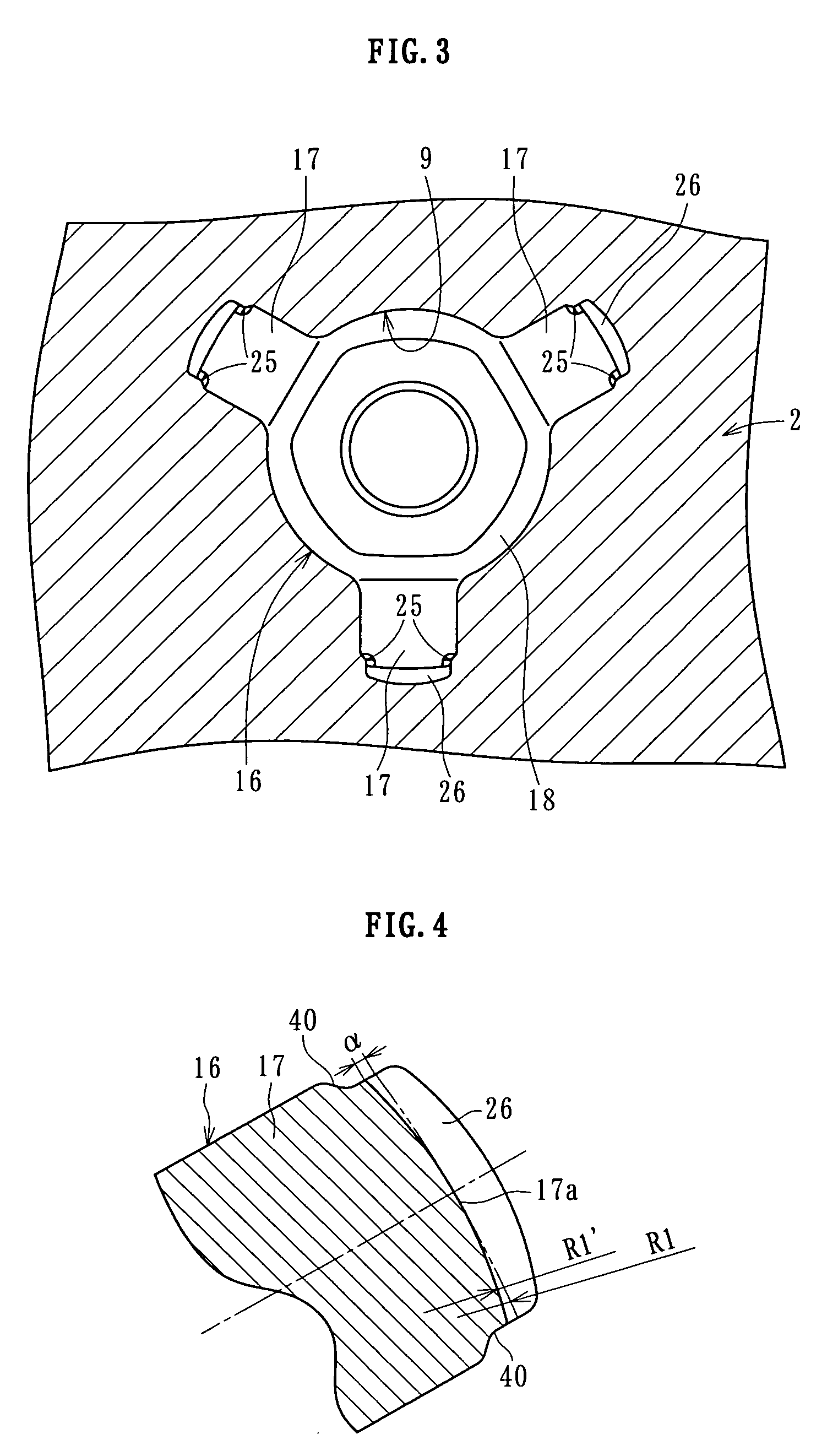
[0048]A state of “sagging” in the case of performing the preliminary molding as shown in FIGS. 7A to 7D was compared to a state of “sagging” in a case of not performing the preliminary molding. Table 1 shows the result. In Table 1, “billet radius of curvature R2” represents the radius of curvature of the material 20B before the preliminary molding (i.e., radius of curvature of conventional material 10 shown in FIG. 9), “premolding radius of curvature R1” represents the radius of curvature of the preliminary-molded material 20A, “shaft end radius of curvature R3” represents the radius of curvature of the tip surface of the molded shaft portion 17, and “sagging” represents a difference between an outermost apex of the tip surface of the molded shaft portion 17 and an outer circumferential rim thereof

[0049]

TABLE 1PremoldingPremolding notperformedperformedBillet radius of curvature16.016.0R2Premolding radius of47.8—curvature R1Shaft end radius of30.522.1curvature R3Sagging1.42.1

[0050]As...


PUM

PropertyMeasurementUnit
circumferenceaaaaaaaaaa
radius of curvatureaaaaaaaaaa
shapeaaaaaaaaaa

Abstract

A closed forging die and a forging method with which sagging can be reduced, a constant velocity joint and a universal joint can be made compact and lightweight, removal of a shaft tip thereof by machining prior to heat treatment is not required, and material costs and machining costs can be reduced by using a closed forging die includes openable dies, and punches that move in an opening / closing direction of the dies to pressurize a material in the dies. By using the die, a product having shaft portions formed radially is manufactured. A clearance is provided to each of the formed shaft portions between a tip surface, and abutting portions are provided to the dies side abutting against at least a tip side of an outer circumferential surface of the shaft portions.

Description

BACKGROUND OF THE INVENTION[0001]1. Field of the Invention[0002]The present invention relates to a closed forging die and a forging method.[0003]2. Description of the Related Art[0004]In manufacturing a product having a boss portion radially provided with shaft portions, such as a trunnion for a constant velocity joint or a cross spider for a universal joint, by closed forging, a closed forging die is used.[0005]As shown in FIG. 8, the closed forging die includes openable dies 1 and 2, and punches 4 and 5 arranged so as to be capable of being driven along center axes of the dies 1 and 2, respectively. That is, by pressurizing a material therein by the punches 4 and 5 while the dies 1 and 2 are in a closed state, a cavity 9 corresponding to configurations of shaft portions 7 and a boss portion 8 of a product 6 is molded. Thus, as shown in FIG. 9A, in a case where, after introducing a billet (material) 10 (refer to FIG. 9A) in the dies 1 and 2, clamping is performed and then the bille...

Claims


Application Information

Patent Timeline
Patent Type & Authority Patents(United States)
IPC IPC(8): B21D22/00
CPCB21J5/02B21K1/762B21K1/763
Inventor JIAHUA, MIAOSERA, AKIRASUZUKI, NOBUO
Owner NTN CORP
Why Eureka
Try Eureka