
Hybrid drive for hydraulic power

a technology of hydraulic power and hybrid drive, which is applied in the direction of hybrid vehicles, fluid couplings, piston pumps, etc., can solve the problems of many tasks facilitated by hydraulic system operation that involve work of a prolonged duration, power supplies on-board the work vehicle are often inadequate to drive the hydraulic system for the duration of work,

Active Publication Date: 2011-03-08
TEREX SOUTH DAKOTA
View PDF15 Cites 147 Cited by
  • Summary
  • Abstract
  • Description
  • Claims
  • Application Information

AI Technical Summary

Benefits of technology

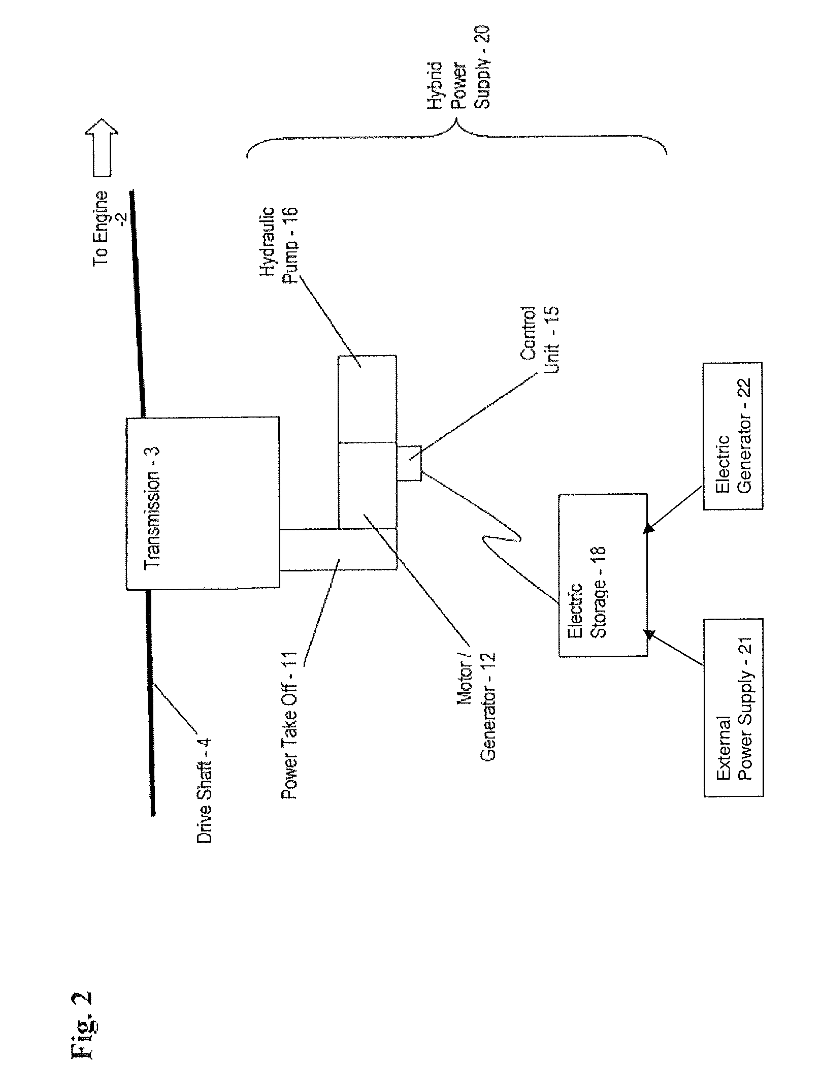
The patent text describes a power supply system for powering a hydraulic implement, such as a vehicle. The system includes an electric storage unit, an electric motor, an electric generator, a hydraulic pump, and a control unit. The electric motor drives the hydraulic pump to power the hydraulic implement, while the electric generator converts mechanical energy from the vehicle's power take off into electric power. The electric storage unit provides the electric power, and the control unit selects between the generator and the storage unit for powering the electric motor. This system allows for efficient and effective powering of hydraulic implements, even in situations where the vehicle's power take off is not available.

Problems solved by technology

However, such hydraulic systems are not without disadvantages.
Consider that many tasks facilitated by operation of hydraulic systems involve work of a prolonged duration.
Accordingly, power supplies on-board the work vehicle are often inadequate to drive the hydraulic system for the duration of the work.
Unfortunately, this is not economic in terms of fuel consumption or vehicle wear.
Further, this is of increasing concern to regulatory agencies.
Given the great variety of these rules, operators of work vehicles are challenged to rely upon traditional methods for powering hydraulic systems on-board work vehicles.
Unfortunately, the technology provided in this example has certain drawbacks.
By way of example, having a powertrain system that includes the second prime mover, such as an electric or hydraulic motor, may cause excess wear and inefficient operation, among other things.

Method used


Image

  • Hybrid drive for hydraulic power
  • Hybrid drive for hydraulic power
  • Hybrid drive for hydraulic power

Examples


Embodiment Construction

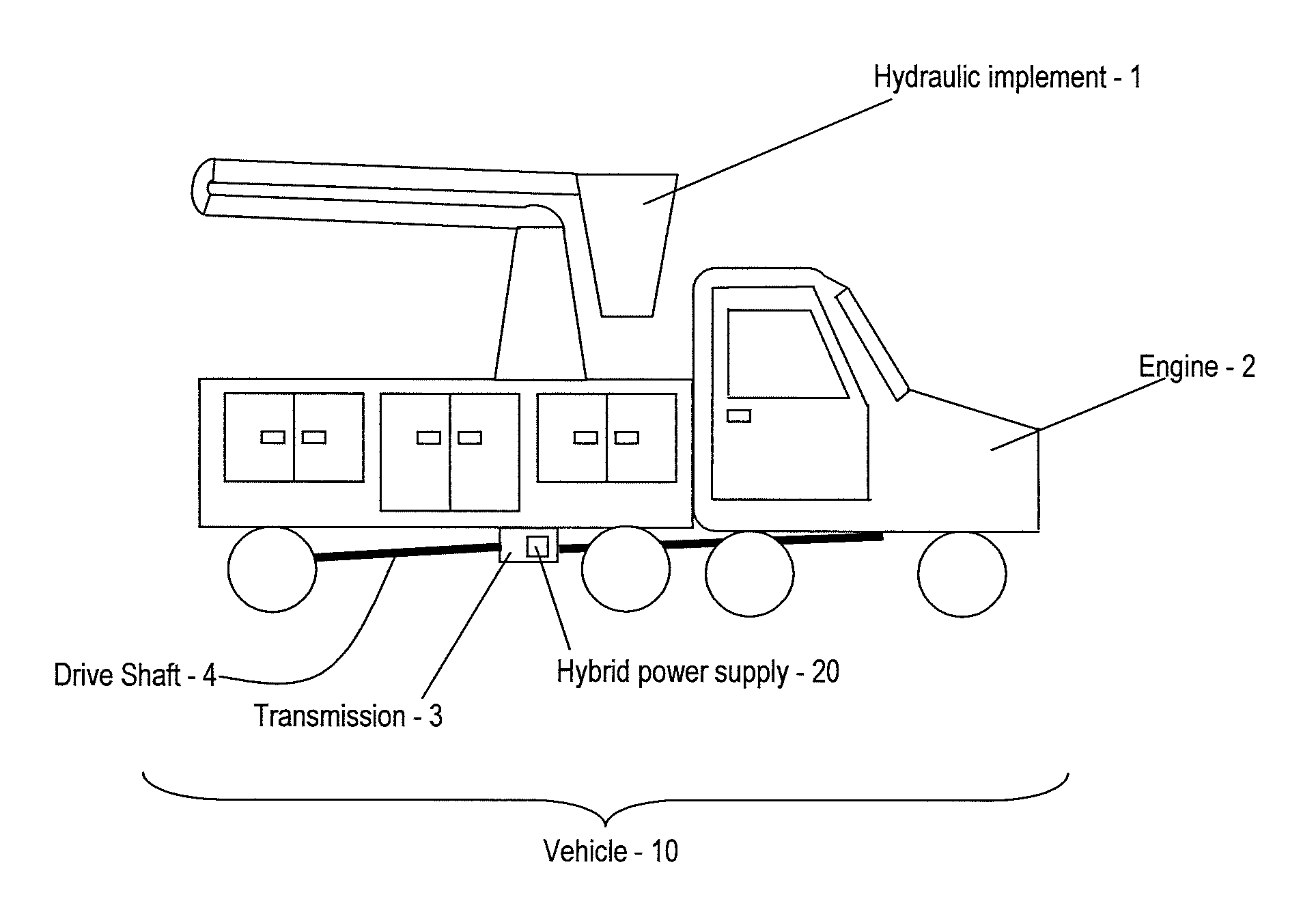
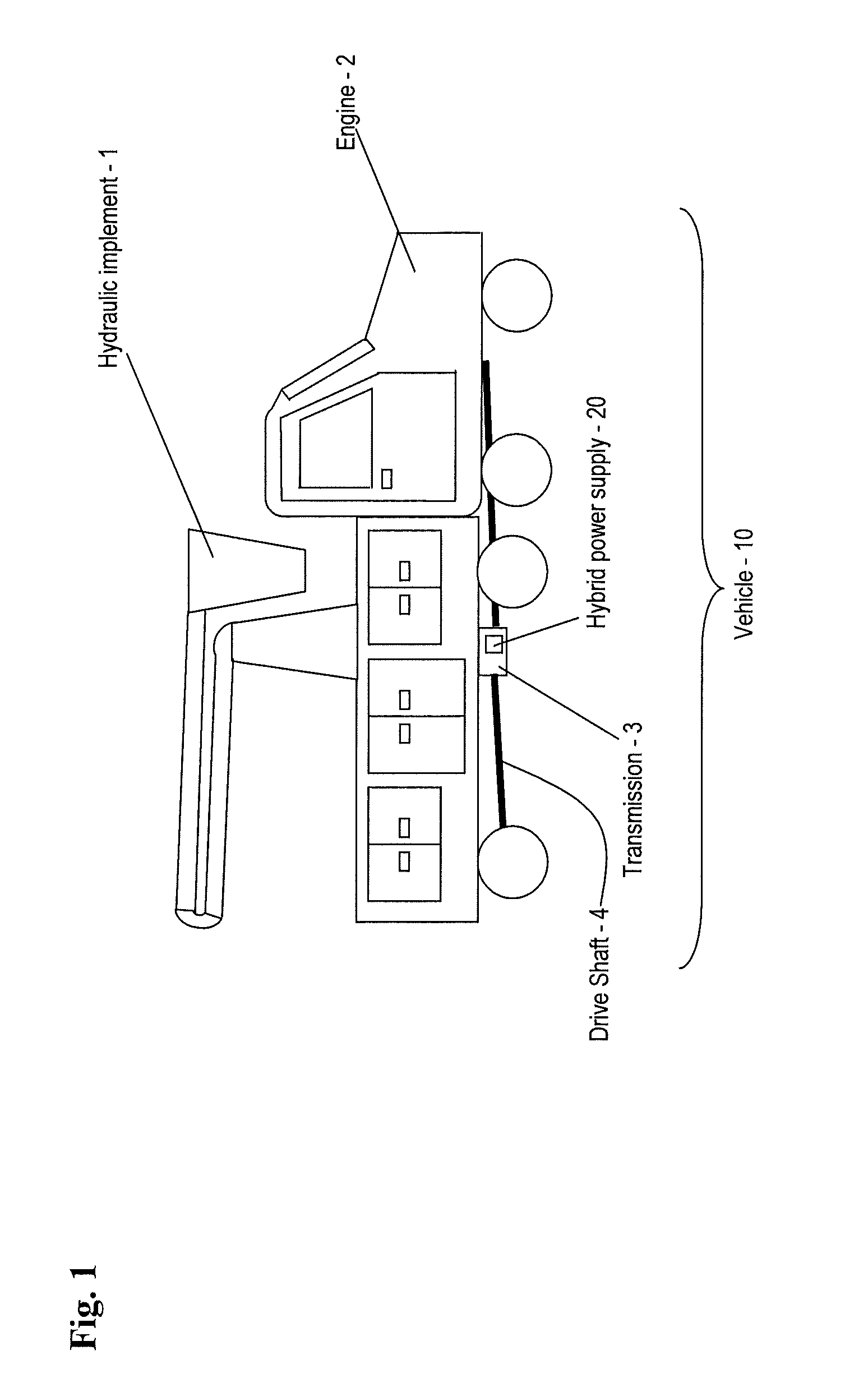
[0015]The teachings herein provide a hybrid power supply for driving a hydraulic system. In the examples provided herein, the hydraulic system is implemented on a work vehicle, such as a utility truck to power a hydraulic implement. Advantageously, the hybrid power supply may be added to an existing vehicle as a retrofit, and therefore need not be integrated into a vehicle, such as at the time of manufacture. One skilled in the art will recognize that the embodiments provided are merely illustrative and are not limiting of the invention. FIGS. 1 and 2 provide an illustrative embodiment of the hybrid power supply.

[0016]Turning now to FIG. 1 there is shown an embodiment of a vehicle 10. The vehicle 10 includes a hydraulic implement 1. In this example, the hydraulic implement 1 is a bucket lift which provides mobility to a user.

[0017]In this embodiment, the vehicle 10 includes an engine 2, a transmission 3 and a drive shaft 4. The engine 2, transmission 3 and drive shaft 4 cooperate as...


PUM


Abstract

A power supply for powering a hydraulic implement includes: an electric storage unit; an electric motor, an electric generator, a hydraulic pump and a control unit; the electric motor adapted for receiving electric power and driving the hydraulic pump to power the hydraulic implement; the electric generator adapted for translating mechanical energy into the electric power; the electric storage unit also being adapted for providing the electric power; and the control unit for selecting a source of the electric power from one of the generator and the electric storage unit. A method for operating the power supply and a vehicle are also provided.

Description

BACKGROUND OF THE INVENTION[0001]1. Field of the Invention[0002]This invention relates to hydraulic drives, and particularly to a hydraulic drive that is driven by a hybrid power supply.[0003]2. Description of the Related Art[0004]Many work vehicles make use of hydraulic systems. For example, consider a traditional utility truck used for servicing residential telephone, electric and cable supplies. Such vehicles with hydraulic systems on-board are virtually ubiquitous in industry. The hydraulic systems provide users with a number of advantages, such as rapid deployment, convenience of use, as well as a robust power supply for tooling (such as hydraulically driven drills). However, such hydraulic systems are not without disadvantages.[0005]Consider that many tasks facilitated by operation of hydraulic systems involve work of a prolonged duration. Accordingly, power supplies on-board the work vehicle are often inadequate to drive the hydraulic system for the duration of the work. One ...

Claims


Application Information

Patent Timeline
Patent Type & Authority Patents(United States)
IPC IPC(8): B60K25/06
CPCB60K6/48B60K25/06F04B9/02F04B17/03F04B17/05H01M16/006H01M2250/20Y02T10/6221Y02T90/32Y02E60/10Y02E60/50Y02T10/62Y02T90/40
Inventor PROMERSBERGER, JONPANTZKE, JOHN
Owner TEREX SOUTH DAKOTA
Learn More