Pump control system

a control system and pump technology, applied in the direction of pump control, non-positive displacement fluid engine, pump control, etc., can solve the problems of poor priming characteristics of pumps, high cost of providing such a sensor that is accurate at a range of flows, and may not be economically practical in many applications. , to achieve the effect of reducing pressure fluctuation and ensuring the accuracy of flow

Inactive Publication Date: 2011-03-08
GRAY
View PDF17 Cites 18 Cited by
  • Summary
  • Abstract
  • Description
  • Claims
  • Application Information

AI Technical Summary

Benefits of technology

[0014]The low pressure transducer may be located directly on the reservoir. In this case it will measure liquid head directly and hence the stored volume of liquid in the reservoir may be computed by the controller. The low pressure transducer may however be advantageously located near the inlet to the pump. In this case it will measure the liquid head above it and hence stored volume of liquid under no flow conditions. When flow is being drawn from the reservoir the pressure recorded by the low pressure transducer will be depressed due to pressure losses induced by flow in the conduit from the reservoir. As such, the pressure depression may be directly related to the flow. This is a good indicator of higher flows but because the pressure depression is related to the square of the flow rate, it is not so accurate at lower flow rates. A highly accurate pressure transducer may however achieve adequate determination of flow.
[0015]The high pressure transducer is attached to the downstream side of the non-return valve. The high pressure transducer is used to measure pressure in the plumbing circuit. The use of a pressure transducer rather than a switch in this location brings significant benefits. It permits a continuous sensing of pressure that enables the rate of change of pressure to be deduced. This has particular benefits as will be described.
[0016]In the event that pressure is drawn down rapidly by a demand on the plumbing circuit, it is desirable to turn the pump on as quickly as possible so as to avoid the pressure declining to a low level. This may be achieved by sensing the rate of pressure decline in the outlet plumbing circuit. Thus, the controller monitors the high pressure sensor and if the pressure decline rate is sufficiently rapid, it turns on the pump even if the pressure has not yet reached a lower threshold. The advantage of this is reduced pressure fluctuation and hence more even flow rate.
[0024]If the pump is on and pressure is declining at the high pressure transducer and reaches the minimum static head permitted by the downstream plumbing, then it may be deduced that the pump is not pumping effectively, probably due to a lack of prime. If at the same time the low pressure transducer near the pump inlet detects a pressure that approaches and reaches that associated with an empty reservoir, then it can be reliably concluded that the pump has lost prime. In a typical water supply situation with a pump delivering water from a tank at a higher level than the pump, then this inlet pressure would correspond to atmospheric pressure. If however the inlet plumbing contained a U-bend, then the possibility exists for the pressure to be negative. This has occurred because the pump has drawn water from the reservoir and has pulled through a slug of air which has caused the pump to loose prime and fail to generate a vacuum. The water in the inlet conduit settles back to and generates a negative inlet pressure (with respect to atmospheric pressure) at the pump inlet. This is because the presence of the non-return valve above the outlet of the pump prevents pressure balancing to occur. In the event of loss of prime as deduced by measuring these characteristics, the pump will be turned off to prevent pump damage and save energy.
[0028]It is advantageous to protect the pump motor by incorporating a voltage sensor into the controller that will protect the pump motor from over and under supply voltage circumstances. It is also beneficial to attach a temperature sensor to the pump motor and to use the controller to monitor the motor temperature. In the event that the pump. motor becomes excessively hot, the pump can be shut down by the controller before any damage occurs. Also, in the event that the temperature drops low enough to lead to the pumped fluid freezing, the pump motor can be prevented from starting.
[0030]The system may also enable lack of prime situations to be remedied by including a de-airing valve that is placed close to the pump outlet and that is opened by the controller. Its purpose is to enable liquid to easily flow through the pump so as to clear air from the pump.

Problems solved by technology

These pumps generally have poor priming characteristics and would normally not prime without fluid at the inlet to the pump.
Whilst the use of flow sensors is highly desirable, the cost of providing such a sensor that is accurate at a range of flows is quite high and may not be economically practical in many applications.

Method used


Image

  • Pump control system
  • Pump control system
  • Pump control system

Examples


Embodiment Construction

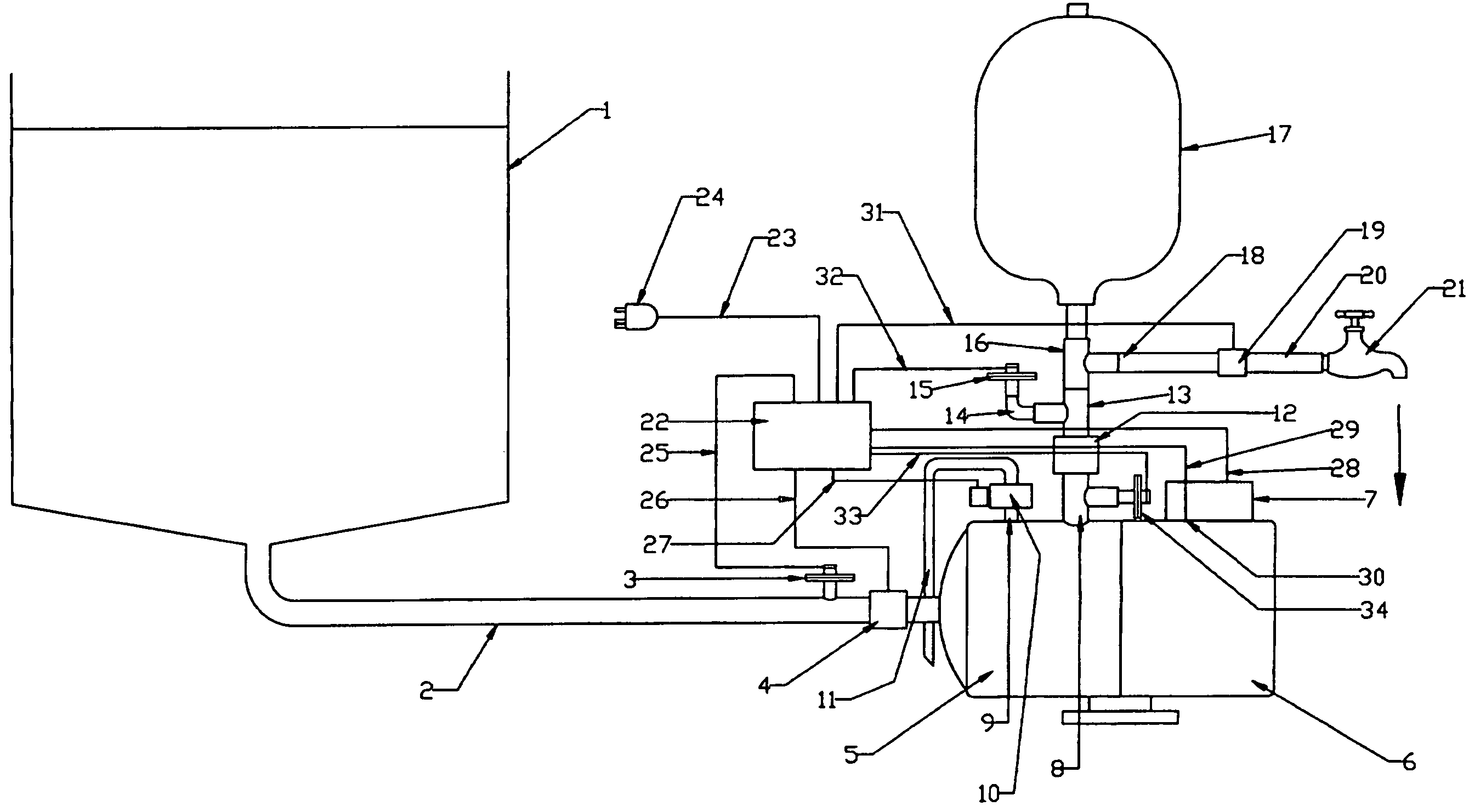
[0041]FIG. 1 is a schematic drawing of the components of a pump system according to one embodiment of the invention. Shown is a reservoir in the form of a tank (1) with an outlet to conduit (2). Attached via a port to this conduit (2) are a pressure transducer (3) and an optional flow meter (4). The conduit (2) feeds liquid into a pump (5), shown as a centrifugal type pump, which is driven by an electric motor (6) equipped with a terminal box (7). This particular pump (5) is of a centrifugal type with a main outlet port (8) and de-airing port (9). The purpose of the de-airing port (9) is normally to manually bleed air out of the pump impeller housing. This port is normally blocked. Above the main outlet port (8) is a non-return valve (12). It should be appreciated that pumps not fitted with de-airing port (9) could equally well be bled of air by the fitting of a tee between the main outlet port (8) and the non-return valve (12). This tee would be connected to a de-airing valve. In t...


PUM


Abstract

A pumping system in which a pump (5) is controlled by a programmed controller (22) in response to input signals from an inlet pressure transducer (3) and an outlet pressure transducer (15) and in certain circumstances inputs from various flow sensors (4,19). The controller (22) can be programmed to allow the pump (5) to prematurely operate before an outlet pressure reaches a low pressure threshold, when usage of the liquid is high. The controller (22) can be programmed to detect a lack of prime of the pump (5), to restore prime once the pump (5) has lost prime, and to prevent successive on / off pump cycles when the outlet flow is continuous and at a moderate or low level.

Description

BACKGROUND OF THE INVENTION[0001]Small water supply systems typically draw water from a reservoir of some sort and pressurise it by means of a pump which discharges the water into a plumbing circuit. Many industrial systems pump liquids other than just water by similar means. To avoid having to run the pump continuously, the pump usually discharges through a non-return valve to a plumbing circuit which incorporates a hydraulic accumulator which is a pressurised storage vessel. Also incorporated into the circuit downstream of the non return valve is a pressure sensitive switch which turns the pump on and off. The switch is designed to turn the pump on at some lower pressure and to turn it off when the pressure exceeds a higher pressure. If the flow from the plumbing circuit is sufficient, then the pressure in the circuit will not exceed the higher pressure threshold and the pump will continue to run. If a tap or other means of drawing flow from the circuit is opened, then flow will b...

Claims


Application Information

Patent Timeline
Patent Type & Authority Patents(United States)
IPC IPC(8): F04B49/00
CPCF04D15/0209
Inventor GRAY
Owner GRAY
Why Eureka
Try Eureka