Fuel cell

a fuel cell and cell technology, applied in the field of fuel cells, can solve problems such as difficulty in reading compressive load, and achieve the effect of improving the operability of assembly and smooth reading

Inactive Publication Date: 2011-03-08
TOYOTA JIDOSHA KK
View PDF14 Cites 10 Cited by
  • Summary
  • Abstract
  • Description
  • Claims
  • Application Information

AI Technical Summary

Benefits of technology

[0008]The present invention has been developed in view of the above situation, and an object thereof is to provide a fuel cell in which a compressive load to be imparted to a cell laminated body can smoothly be read.
[0012]According to such a constitution, even when the storage space of the elastic member is closed, the protruding amount of the display member from the outer surface of the other plate member can visually be checked from the outside to easily grasp the compressive load.
[0014]According to such a constitution, the protruding amounts of the display members of the load display sections provided in the plurality of positions can be measured to smoothly grasp the compressive load exerted to the cell laminated body, and the tilts of the plate members can be grasped, so that the balance of the compressive load can be grasped.
[0016]According to such a constitution, all the load display sections can visually be checked from the predetermined direction to grasp the balance of the compressive load. Moreover, the respective load display sections can be adjusted while visually checking the sections from the predetermined direction, so that the assembling operability of the pressing device can be improved.
[0017]According to the fuel cell of the present invention, the compressive load to be imparted to the cell laminated body can smoothly be read.

Problems solved by technology

However, in the above spring module, a compressive load is read on the side of one side surface provided with graduations, the one side surface provided with the graduations is covered, depending on the arranged state of a fuel cell or the received state of the fuel cell in a case, and it is therefore difficult to read the compressive load.

Method used


Image

  • Fuel cell
  • Fuel cell
  • Fuel cell

Examples


Embodiment Construction

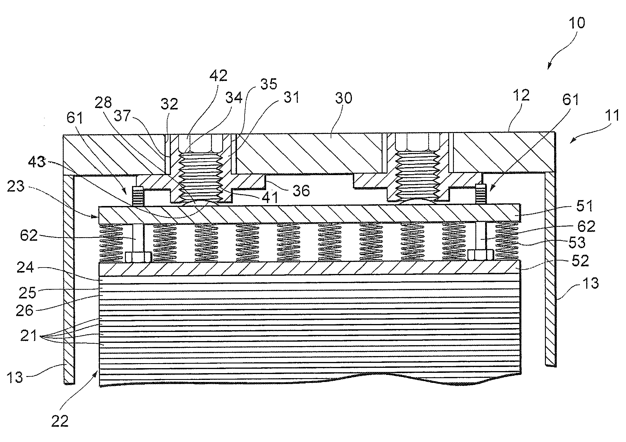
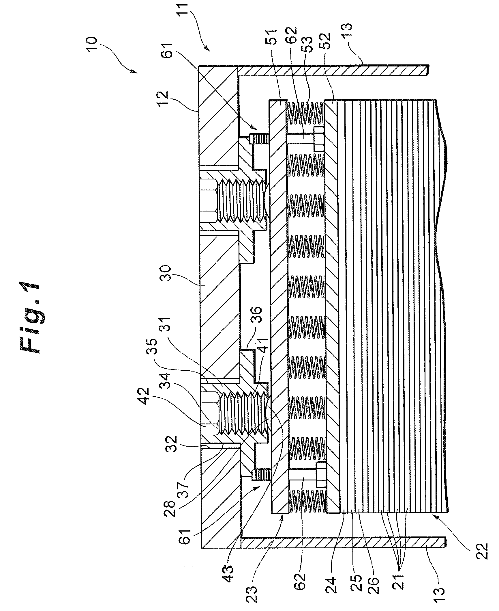
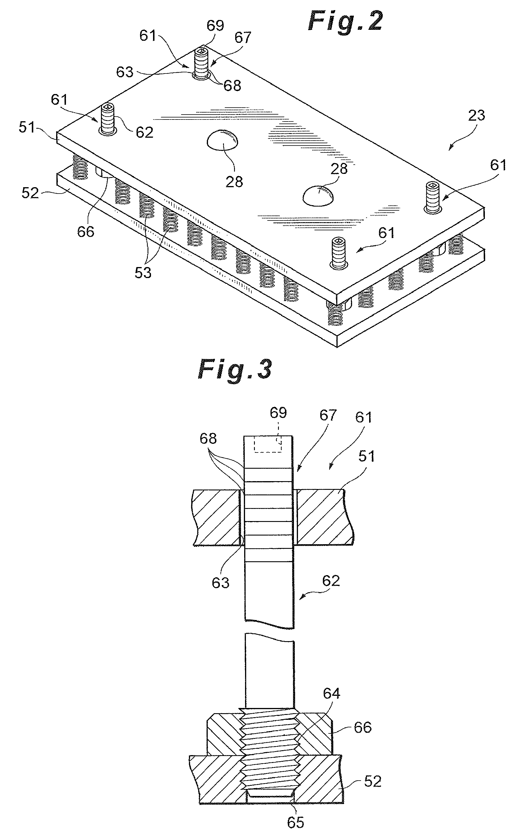
[0025]Next, a first embodiment of a fuel cell according to the present invention will be described with reference to FIGS. 1 to 3.

[0026]FIG. 1 shows a fuel cell 10. This fuel cell 10 is applicable to a car-mounted power generation system of a fuel cell car, a power generation system for any mobile body such as a ship, an airplane, a train or a walking robot, a stational power generation system for use as a power generation facility for a construction (a housing, a building or the like) or the like, but the fuel cell is specifically used for a car.

[0027]The fuel cell 10 has a fuel cell stack 11, and a stack case (not shown) constituted of an insulating material such as a synthetic resin which covers this fuel cell stack 11. In the fuel cell stack 11, the outer edges of a pair of rectangular end plates 12 (one of them is omitted from the drawing) are connected to each other via tension plates 13 to constitute an outer part, and the end plates 12 and the tension plates 13 are made of, ...


PUM

PropertyMeasurementUnit
compressiveaaaaaaaaaa
elastic forceaaaaaaaaaa
structureaaaaaaaaaa

Abstract

A fuel cell is provided with a cell laminated body in which a plurality of cells are laminated, an end plate arranged outside the cell laminated body in a laminating direction; and a spring module which is arranged between the cell laminated body and the end plate so as to adjust a compressive load to the cell laminated body. The spring module is provided with coil springs which are arranged between an upper plate and a lower plate so as to separate the upper plate and the lower plate from each other by an elastic force. The spring module is provided with a plurality of load display sections having display shafts which are fixed to the lower plate, inserted into through holes of the upper plate and protrude from the outer surface of the upper plate on an end plate side.

Description

[0001]This is a 371 national phase application of PCT / JP2007 / 062647 filed 18 Jun. 2007, which claims priority to Japanese Patent Application No. 2006-170514 filed 20 Jun. 2006, the contents of which are incorporated herein by reference.TECHNICAL FIELD[0002]The present invention relates to a fuel cell having a cell laminated body in which power generation cells are laminated.BACKGROUND ART[0003]In recent years, a fuel cell car or the like has received attention in which a fuel cell for generating a power by an electrochemical reaction between a fuel gas and an oxidizing gas is used as an energy source.[0004]Such a fuel cell is usually constituted as a fuel cell stack including a cell laminated body in which the required number of cells for generating the power by the electrochemical reaction between the fuel gas and the oxidizing gas are laminated, and an end plate which is arranged outside this cell laminated body in a laminating direction and which imparts a compressive load adjust...

Claims


Application Information

Patent Timeline
Patent Type & Authority Patents(United States)
IPC IPC(8): H01M8/24
CPCH01M8/248Y02E60/50
Inventor INAGAKI, TOSHIYUKI
Owner TOYOTA JIDOSHA KK
Why Eureka
Try Eureka