Remotely-controlled traffic control system

a remote control and traffic control technology, applied in the direction of traffic signals, roads, instruments, etc., can solve the problems of serious injury or death, inability to recognise the tcp's themselves are at risk, so as to increase the recognisability of the unit as a tcp, reduce construction costs, and increase worker safety

a remote control and traffic control technology, applied in the direction of traffic signals, roads, instruments, etc., can solve the problems of serious injury or death, inability to recognise the tcp's themselves are at risk, so as to increase the recognisability of the unit as a tcp, reduce construction costs, and increase worker safety

US7902998B2Inactive Publication Date: 2011-03-08VISION TRAFFIC TECH INC

Image

  • Remotely-controlled traffic control system
  • Remotely-controlled traffic control system
  • Remotely-controlled traffic control system

Examples


Embodiment Construction

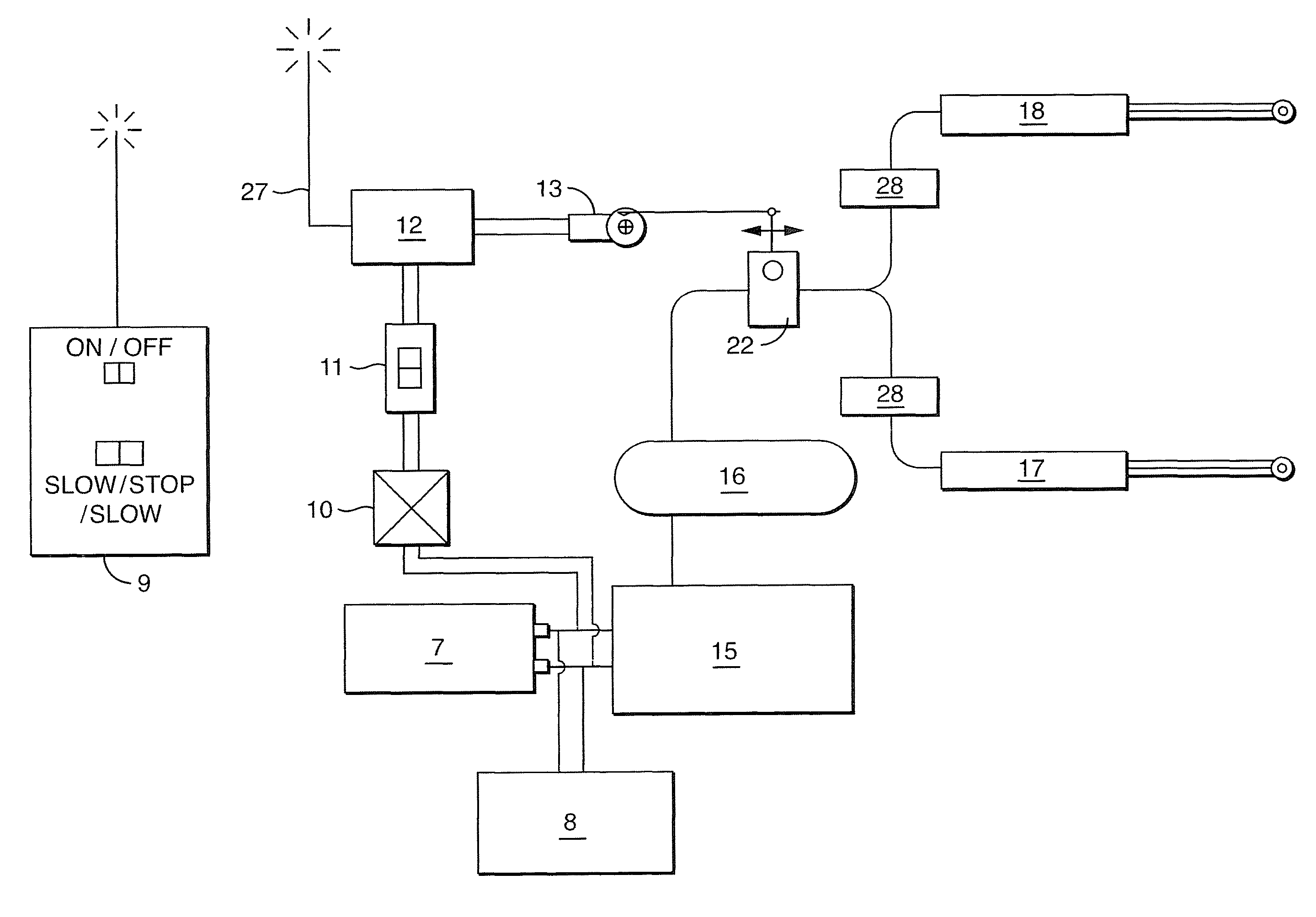
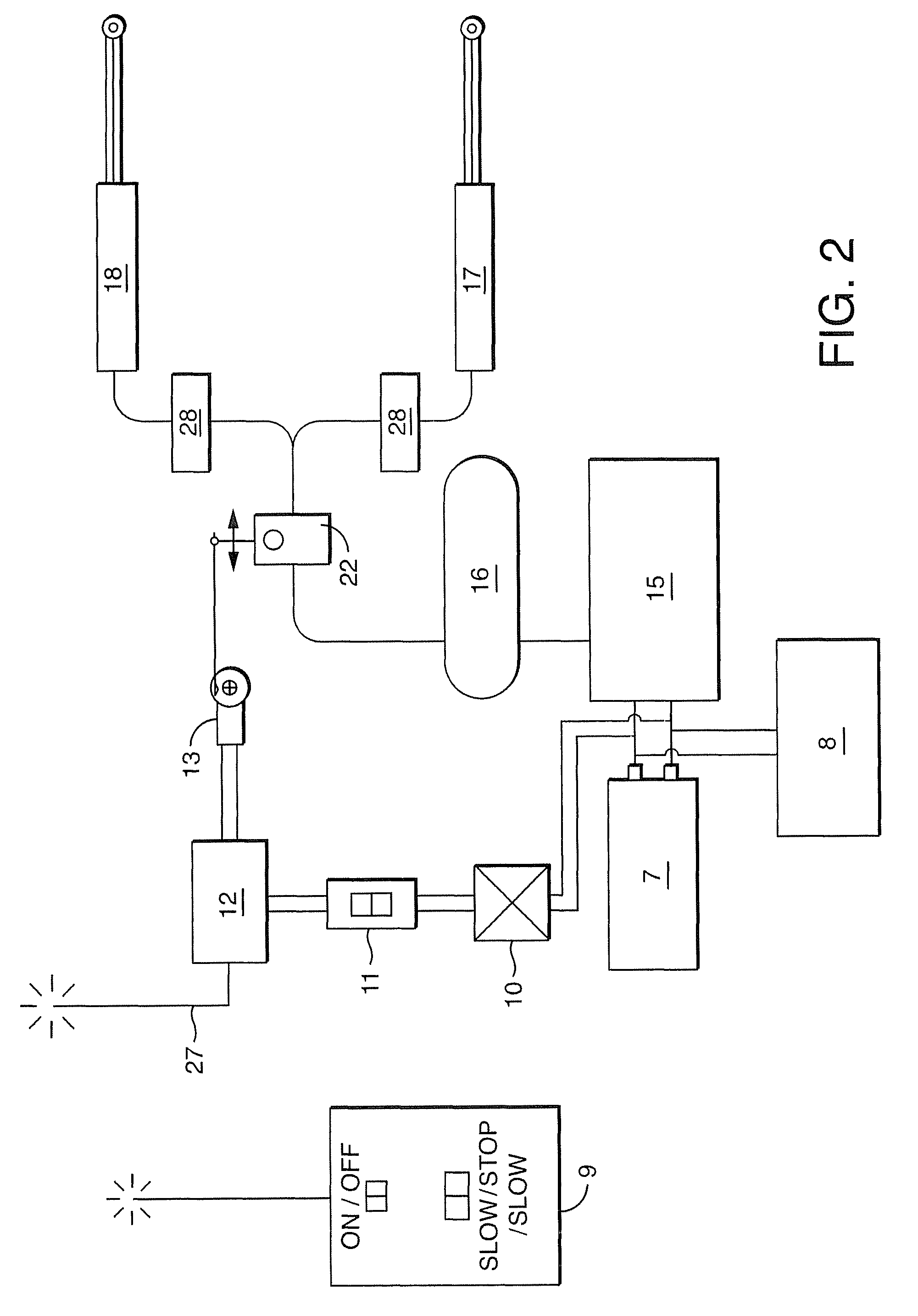
[0028]Although other applications may be envisioned for the traffic control system of the present invention, such as a system to control traffic that requires adaptation to various environments, the use of the system of the present invention is particularly advantageous in terrains requiring mobility of the system and adaptation thereof. Accordingly, without intending to limit the present invention to the embodiments described herein, the invention will be described below in further detail having regard to the adjustable traffic control system and devices thereof shown in FIGS. 1 to 5.

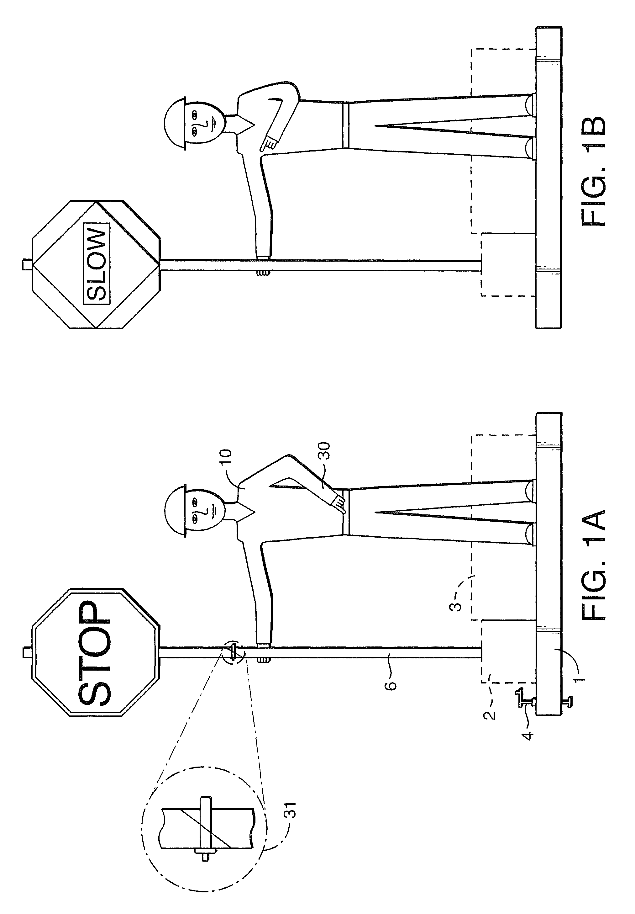
[0029]Referring to FIG. 1 shown is the traffic control system in accordance with a preferred embodiment from the front. The traffic control system has a two-sided sign 6 in both the ‘Stop’ and ‘Slow’ positions. The two-sided sign 6 may be attached to a vertical pole that is supported at the base 1 and hand 29 by bearings. The top portion of the sign 6 may be adapted to be removably and / or rotatably mou...


PUM


Abstract

A system and apparatus controls the movement of vehicles such as highway traffic. The system includes a plurality of inorganic entities which simulate mammalian figures and control apparatus which is operatively associated with the mammalian figures such as to control their respective movement upon activation by an activation assembly. A system actuating means is provided whereby upon selected system actuation the mammalian figures are caused to issue signals to effectively control the movement or arrest of traffic within the effective area of operation of the system.

Description

RELATED APPLICATION[0001]This application claims the benefit of Canadian Provisional Patent Application No. 2,579,973 filed 28 Feb. 2007, the entire contents of which are incorporated herein by reference.FIELD OF THE INVENTION[0002]The present invention relates to an adjustable traffic control system. In particular, the present invention relates to a traffic control system with a remotely-controlled portable, automated traffic control system having a STOP / SLOW sign and movable arm for use at a construction site.BACKGROUND OF THE INVENTION[0003]During construction projects on any road or highway, there is a need and / or, in some jurisdictions, a legal requirement for traffic to be controlled and directed by the contractor or the owner. This traffic control may consist of an assortment of items (Traffic Control Persons, arrow boards, Jersey Barriers, pylons, barrels, temporary portable traffic lights, signage etc.). In the case of a human TCP, they are generally placed at the start of ...

Claims


Application Information

Patent Timeline
08 Mar 2011
Publication
US7902998B2
IPC
G08G1/095; E01F9/646
CPC
G09F7/18; G09F7/22; G09F15/0037
Inventors
WHEATON, BRIAN