Planar antenna device and radio communication device using the same

a technology of radio communication device and planar antenna, which is applied in the direction of individual energised antenna array, substantially flat resonant element, resonant antenna, etc., can solve the problem of narrow intervals and installation of feed lines, and achieve the effect of shortening the feed line, high radiation efficiency and high radiation efficiency

Inactive Publication Date: 2011-03-08
PANASONIC CORP
View PDF17 Cites 8 Cited by
  • Summary
  • Abstract
  • Description
  • Claims
  • Application Information

AI Technical Summary

Benefits of technology

[0034]According to the present invention, a bend does not have to be provided in the feed line, thereby achieving an array antenna structure where a smaller portion is occupied by the feed line. There are no losses due to bends, thereby achieving an array antenna with high radiation efficiency. Furthermore, the portion to be occupied by the feed line can become the smallest possible dimensions, thereby achieving a low-loss array antenna with high radiation efficiency, owing to a shorter feed line. Furthermore, the smaller portion to be occupied by the feed line allows the antenna elements to be arranged at a shorter spacing, thereby allowing a grating lobe of the radiated radio waves to be suppressed.
[0035]Furthermore, according to the present invention, only a smaller portion is occupied by the feed line, a larger space can be provided between the feed lines, or between the antenna and the feed line, thereby reducing interference between the feed lines. This achieves a broadband antenna which was unavailable due to its thicker antenna board and its larger interference between the feed lines.

Problems solved by technology

However, as the interval between the antenna conductors becomes wider, the side lobe of the radio waves radiated from the array antenna increases in level, the feed line has to be installed into the narrow interval limited by the antenna conductors.

Method used


Image

  • Planar antenna device and radio communication device using the same
  • Planar antenna device and radio communication device using the same
  • Planar antenna device and radio communication device using the same

Examples


Embodiment Construction

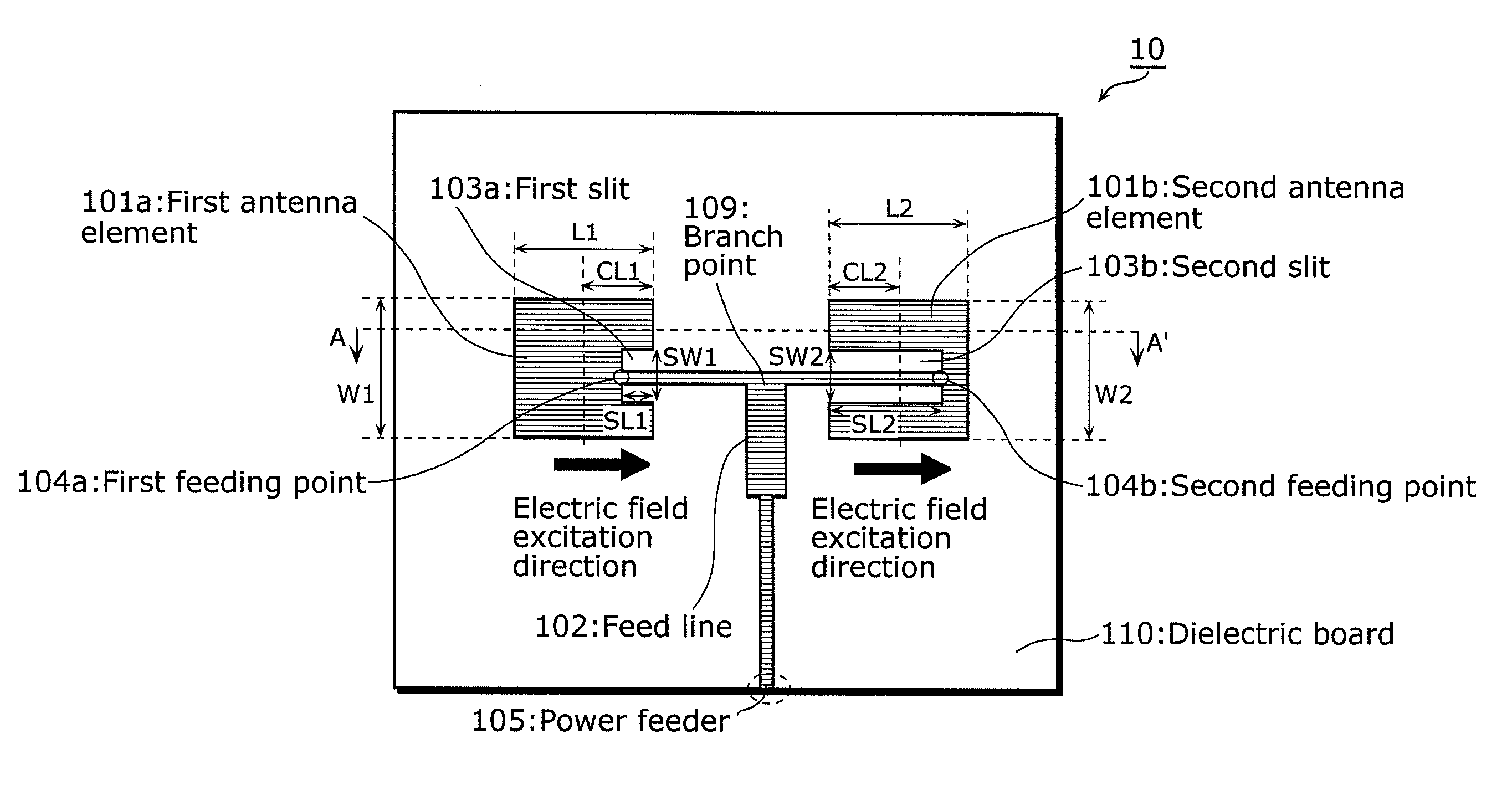
[0073]Hereinafter, a planar antenna device according to the embodiment of the present invention is described with reference to accompanying drawings. Although the description is given for the present invention with the following embodiment and the accompanying drawings, the embodiment and the drawings are given for exemplification; the present invention is not limited to the embodiment and the drawings.

[0074]FIG. 4(a) is a top view showing a planar antenna device 10 according to the present invention. The planar antenna device 10 shown in FIG. 4(a) includes a first antenna element 101a, a second antenna element 101b, a first feeding point 104a, a second feeding point 104b, impedance-matching first slit 103a and second slit 103b, a feed line 102 (a branch point 109 included), a power feeder 105 and a dielectric board 110.

[0075]The first feeding point 104a of the first antenna element 101a is provided on the side of the first antenna element having an edge facing the branch point 109 ...


PUM


Abstract

Provided a practical planar antenna device which has antenna elements facing each other, in which electrical power is fed between the antenna elements. The first feeding point is provided near an end of the first antenna element, which faces the opposite antenna element. The second feeding point is provided near an outer end of the second antenna element, by providing a second slit longer than the distance from the end of the second antenna element to its center. Since the feeding points are provided at the same level, the same electric field is excited in the two antenna elements in phase. The planar antenna device, to which electrical power is fed from the facing sides of the pair of opposite antenna elements, saves a bend conventionally required in a feed line, thereby allowing a wiring area to be smaller than in the conventional method.

Description

TECHNICAL FIELD[0001]The present invention relates to radio communication devices such as a mobile phone, or devices which measure a distance to a target or recognize the position of a target. The present invention particularly relates to a planar antenna device which transmits and receives radio waves used for the above devices.BACKGROUND ART[0002]As a conventional planar antenna device, a thin, lightweight microstrip patch antenna is widely available (For example, see Patent Reference 1). The patch antenna has a structure such that a ground conductor (ground) and a rectangular antenna conductor (also known as an “antenna element”) to serve as an antenna unit are formed on the back and the face side of a dielectric board, respectively. As electrical power is fed to the antenna conductor, radio waves are radiated at a frequency where resonance occurs according to the length of the longer sides of the antenna conductor. In order to feed electrical power to the antenna conductor, the ...

Claims


Application Information

Patent Timeline
Patent Type & Authority Patents(United States)
IPC IPC(8): H01Q1/38
CPCH01Q9/0407H01Q9/045H01Q21/0075H01Q21/065H01Q21/22
Inventor NAGAI, SHUICHI
Owner PANASONIC CORP
Why Eureka
Try Eureka