Supercharge Your Innovation With Domain-Expert AI Agents!

Lens tube, method of assembling lens tube, and camera module

a technology of lens tube and lens frame, which is applied in the field of lens tube, can solve the problems of lens frame inclination, increased tube size, and increased manufacturing cost of the tube, and achieve the effect of preventing lens inclination

Inactive Publication Date: 2011-03-08
SHARP KK
View PDF13 Cites 6 Cited by
  • Summary
  • Abstract
  • Description
  • Claims
  • Application Information

AI Technical Summary

Benefits of technology

The present invention provides a lens tube with high precision between lenses and prevents inclination of the lenses without affecting the optical performance of the tube. The lens tube includes two lenses, a tubular lens frame for holding the two lenses, and three or more spacers which are placed between the two lenses and in contact with opposite lens surfaces. The spacers are fixed to the lenses with adhesive, and the adhesive is applied to the inside of an area of the lens frame that passes the lenses. The adhesive may be a light-shielding resin for impact resistance and prevention of stray light. The invention also provides a method of assembling the lens tube.

Problems solved by technology

However, in the case where the positioning structure 207 (307) is provided in the lens frame 203 (303) as seen in FIG. 14A and FIG. 14B, manufacturing costs of the tube increase with complication of the lens frame configuration.
In order to secure a wider effective area of the lens, the inside diameter of the positioning structure needs to be expanded, and this requires the inside diameter of the lens frame to be expanded, which in turn causes increase in tube size.
However, when steel balls are placed at predetermined positions in the circumferential direction, the motion of the steel balls is not regulated, and therefore the steel balls may move from the predetermined positions during the assembling process, which may generate clearance between the steel balls and the lens frame inner wall and eventually cause inclination of the lenses as in the case of using the space rings.
Moreover, in the case where the surface on which the steel balls 406 are placed is concaved, the motion of the steel balls 406 is not regulated in the circumferential direction nor in the diameter direction, and therefore it also becomes difficult to proceed the assembling process afterward as in the case of the flat surface.

Method used


Image

  • Lens tube, method of assembling lens tube, and camera module
  • Lens tube, method of assembling lens tube, and camera module
  • Lens tube, method of assembling lens tube, and camera module

Examples


first embodiment

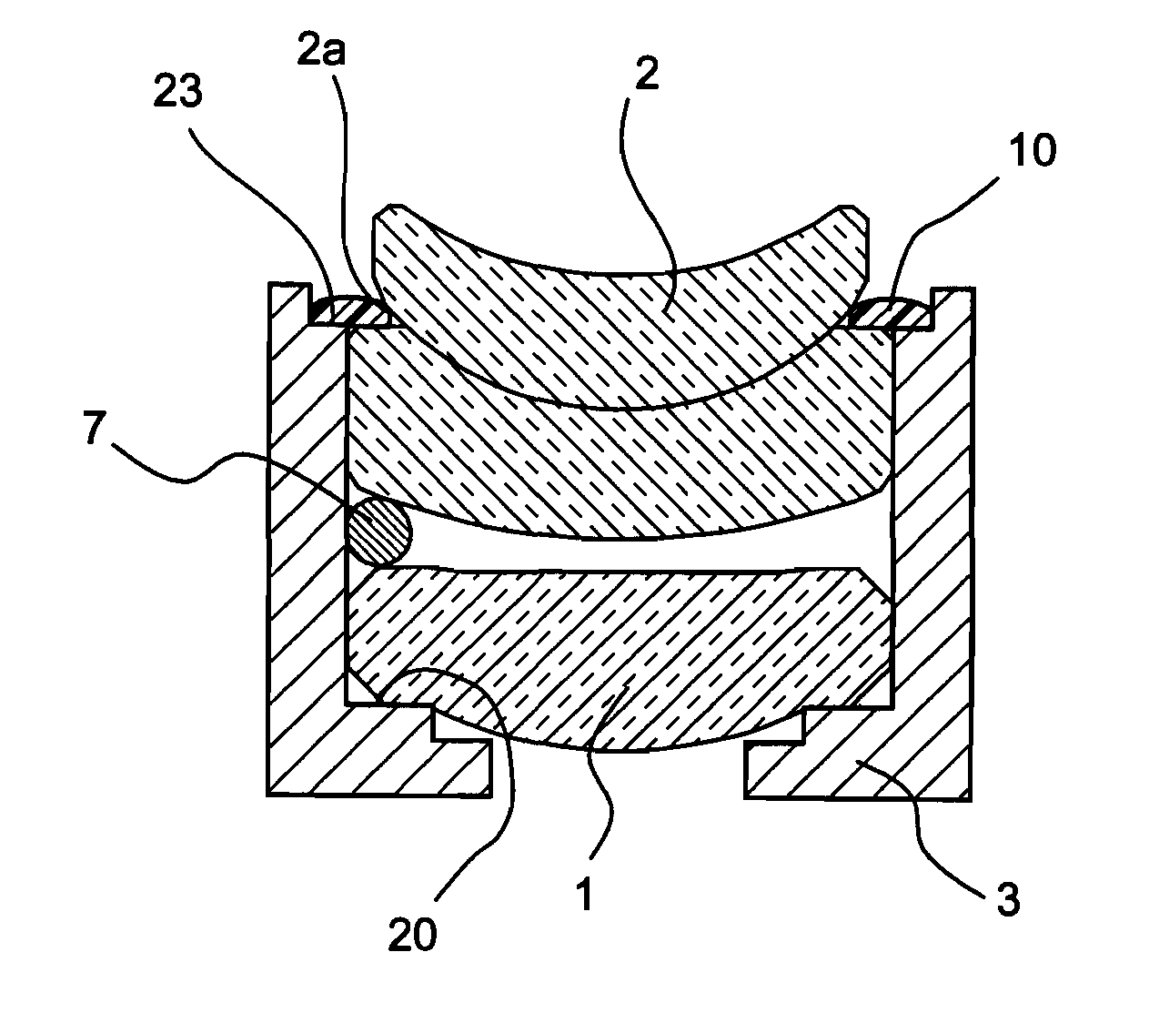
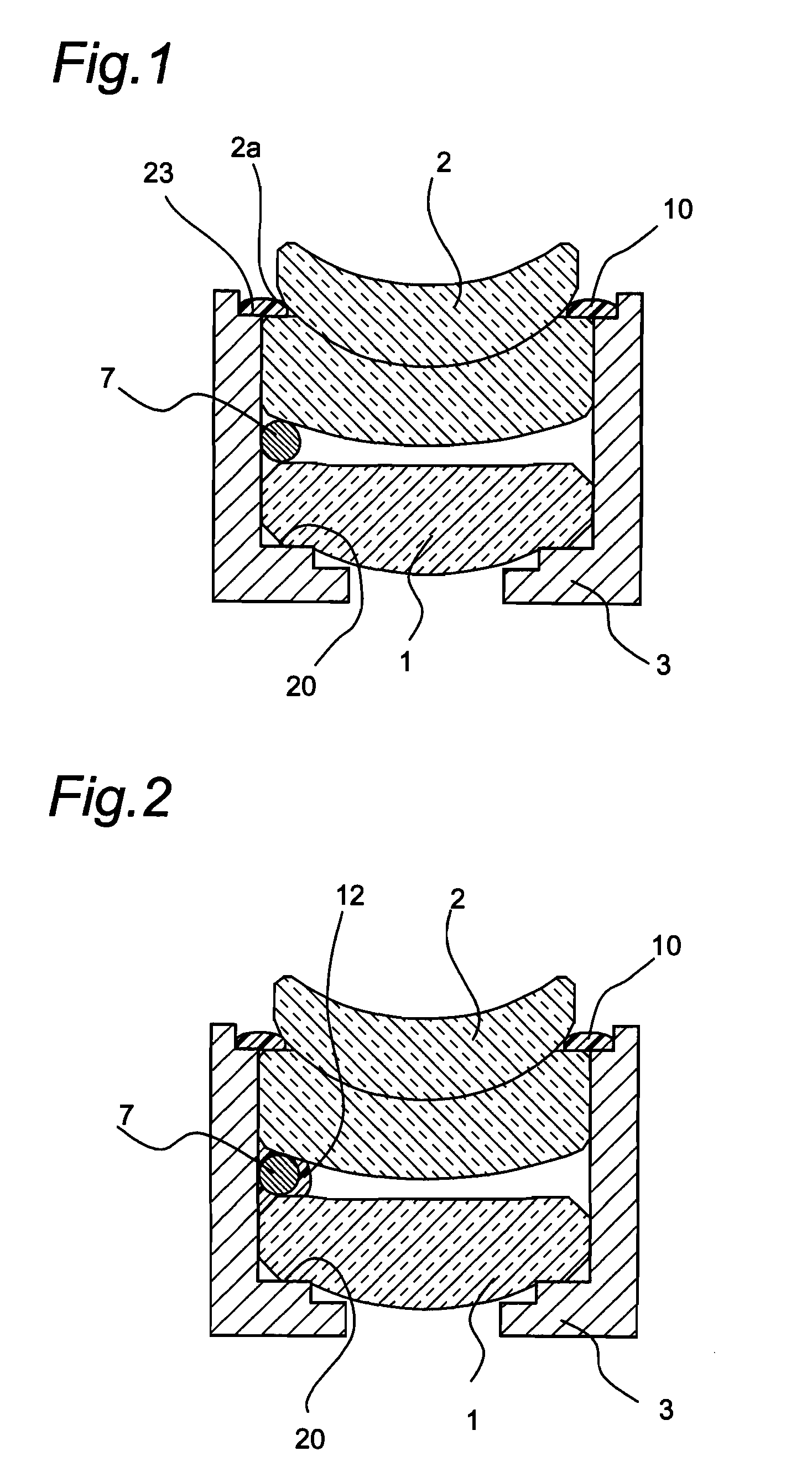
[0117]FIG. 1 shows a cross section of a lens tube in the first embodiment of the invention.

[0118]The lens tube shown in FIG. 1 is composed of two lenses, first lens and second lens, a tubular lens frame 3 for holding each of the first and second lenses 1, 2, and three spherical spacers 7 which are in contact with the opposite lens surfaces of the first and second lenses 1, 2. In this case, the spacers 7 are present in the state of being in contact with the curved surfaces of the first lens 1 and the second lens 2 and determine a distance between the first and second lenses 1, 2. The first lens 1 is a compound lens made up of two optical devices.

[0119]A step section 20 provided in the vicinity of a lower end side of the inner circumference of the lens frame 3 is in contact with a peripheral section of the lens surface of the first lens 1. The spacers 7 are fixed to the first lens 1 with adhesives 10.

[0120]The second lens 2, which is a compound lens, is formed by joining two meniscus ...

second embodiment

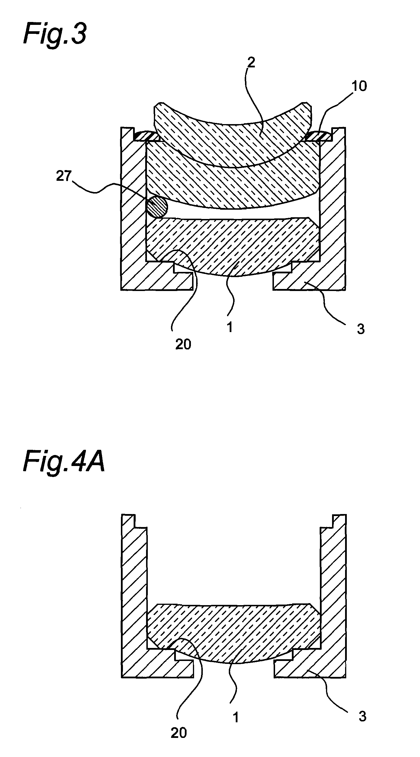
[0131]FIG. 3 shows a cross section of a lens tube in the second embodiment of the invention. The lens tube of the second embodiment is similar in configuration to the lens tube of the first embodiment except for the spacers, and therefore similar component members are designated by similar reference numerals.

[0132]A lens tube shown in FIG. 3 is composed of two lenses, first and second lenses 1, 2, a cylindrical lens frame 3 for holding the first and second lenses 1, 2 with their optical axes aligned with each other, and three spherical spacers 27 which are in contact with the opposite lens surfaces of the first and second lenses 1, 2 and with the inner wall of the lens frame 3. In this case, the spacers 27, which include ferromagnetic materials or ferrimagnetic materials, are present in the state of being in contact with the curved surfaces of the first lens 1 and the second lens 2 and determine a distance between the first and second lenses 1, 2.

[0133]As the ferromagnetic materials...

third embodiment

[0168]FIG. 8 shows a cross section of a lens tube in the third embodiment of the invention. The lens tube of the third embodiment is similar in configuration to the lens tube of the second embodiment except that the spacers are fixed to the lens with adhesives, and therefore similar component members are designated by similar reference numerals.

[0169]A lens tube shown in FIG. 8 is composed of two lenses, first and second lenses 1, 2, a cylindrical lens frame 3 for holding the first and second lenses 1, 2 with their optical axes aligned with each other, and three spherical spacers 27 which come into contact with the opposite lens surfaces of the first and second lenses 1, 2 and with the inner wall of the lens frame 3. The spacers 27 include ferromagnetic materials or ferrimagnetic materials and are fixed to the lens surface of the first lens 1 with adhesives 10.

[0170]Description is now given of the procedures in the method of assembling the lens tube shown in the third embodiment wit...


PUM

PropertyMeasurementUnit
distanceaaaaaaaaaa
massaaaaaaaaaa
inner diameteraaaaaaaaaa

Abstract

A lens tube has two, first and second lenses (1, 2), a tubular lens frame (3) for holding the two lenses (1, 2), and three spacers (7) in contact with the opposite lens surfaces of the first and second lenses (1, 2). The spacers (7) are arranged so as to be in contact with curved surfaces of the first and second lenses (1, 2) and determine the distance between the first and second lenses (1, 2). The lens frame (3) has the same inner diameter between the first and second lenses (1, 2), and the spacers (7) are in contact with the inner wall of the lens frame (3). Since the lens frame (3) has the same inner diameter between the first and second lenses (1, 2), the first and second lenses (1, 2) are held with their centers perfectly aligned with each other.

Description

TECHNICAL FIELD[0001]The present invention relates to a lens tube, a method of assembling the lens tube, and a camera module, and more specifically relates to a lens tube holding a plurality of lenses fixed onto a lens frame, a method of assembling a lens tube, and a camera module using the lens tube.BACKGROUND ART[0002]A conventional lens tube incorporates one lens group or a plurality of lens groups as a photographing optical system. The lens tube is generally assembled from a plurality of lenses, which constitute such a lens group, and a lens frame which incorporates and holds the lenses. A method of assembling the lens tube shown in FIG. 13 is known as a method for incorporating a plurality of lenses, which belong to the lens group of the lens tube, into the lens frame at a predetermined distance. In this method of assembling the lens tube, a lens tube 105 is formed by incorporating lenses 101, 102 into a lens frame 103 from one direction and interposing a space ring 104 which i...

Claims


Application Information

Patent Timeline
Patent Type & Authority Patents(United States)
IPC IPC(8): G02B7/02
CPCG02B7/021H04N5/2257Y10T29/49826H04N23/57
Inventor ABE, RYOMINAMIDE, SHOZOMINAMI, KOHJI
Owner SHARP KK
Features
  • R&D
  • Intellectual Property
  • Life Sciences
  • Materials
  • Tech Scout
  • Unparalleled Data Quality
  • Higher Quality Content
  • 60% Fewer Hallucinations
Learn More