
System for deploying data from deployment-source device to deployment-destination device

a data deployment and destination device technology, applied in the field of data deployment system for deploying data from a deploymentsource device to a deploymentdestination device, can solve the problems of impossible to recover volume images of the versions which follow the missing version, impossible to easily discard (erase), and the entire volume image. achieve the effect of high speed

Inactive Publication Date: 2011-03-08
KK TOSHIBA +1
View PDF7 Cites 0 Cited by
  • Summary
  • Abstract
  • Description
  • Claims
  • Application Information

AI Technical Summary

Benefits of technology

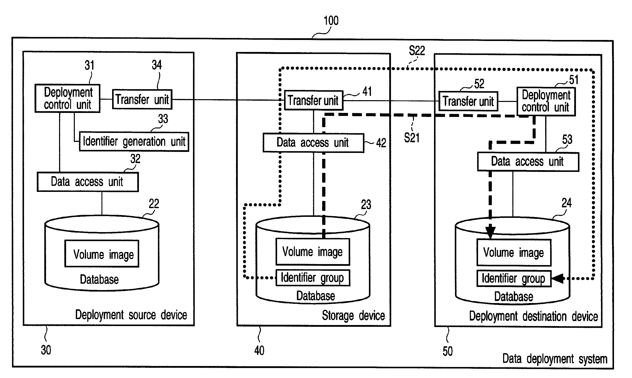
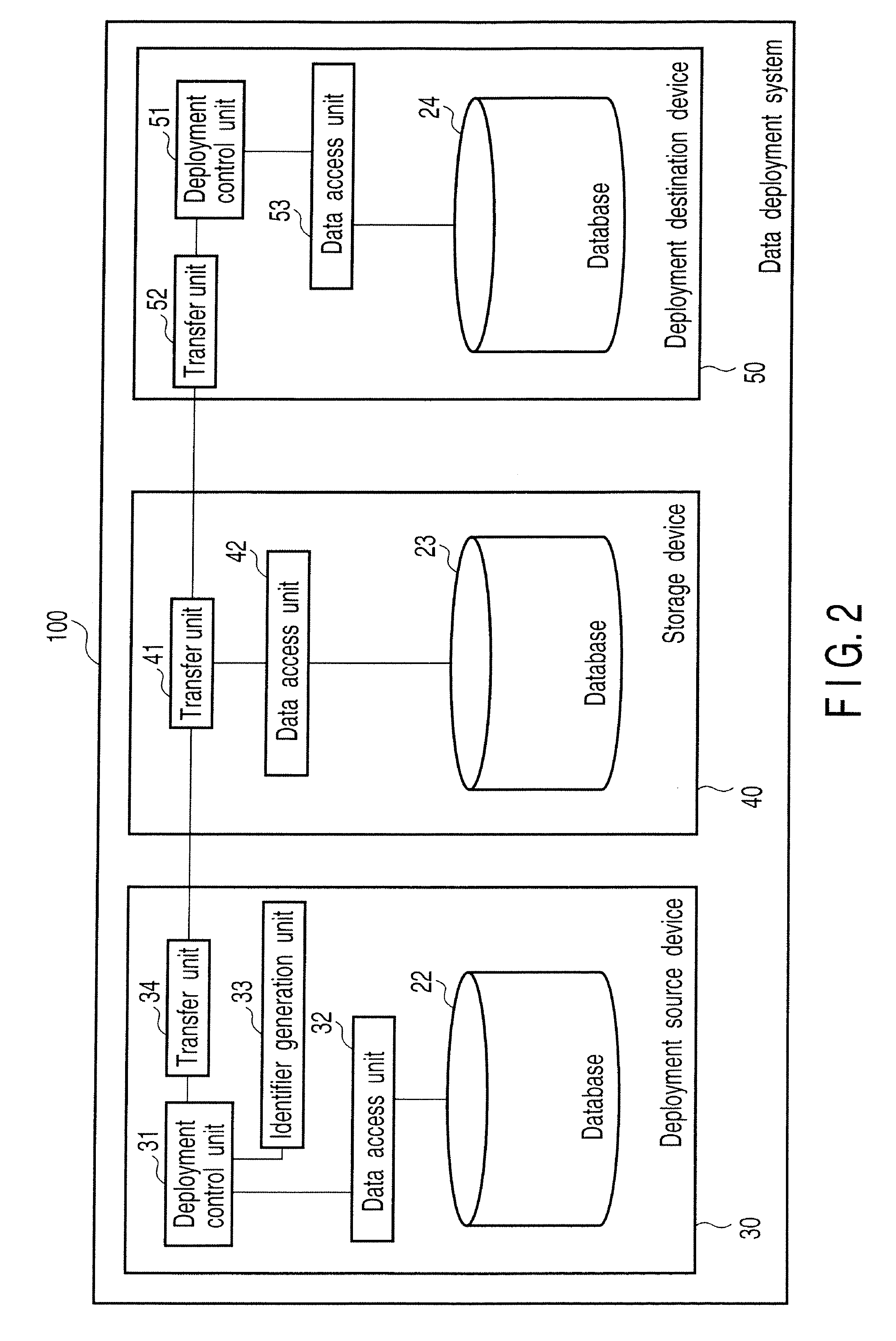
The present invention provides a data deployment system and program that can quickly and efficiently transfer data from one device to another. The system includes a deployment-source device that stores the original data and a deployment-destination device that stores the updated data. The deployment-source device generates unique identifiers for each piece of data and sends them to the deployment-destination device. The device then checks if the identifiers match and, if so, stores the data in its database. This allows for quick and easy deployment of data from one device to another.

Problems solved by technology

In addition, if a differential map of an arbitrary version is missing, it is absolutely impossible to recover volume images of the versions which follow the missing version.
Moreover, since a differential part cannot be transferred if the differential map is missing, it is not possible to easily discard (erase), for instance, even the differential map of the old version.
At this time, for example, if the speed of access to the communication path is sufficiently higher than the speed of access to the database of the deployment-source device or deployment-destination device, the process of reading in the entirety of the volume image results in a bottleneck.

Method used


Image

  • System for deploying data from deployment-source device to deployment-destination device
  • System for deploying data from deployment-source device to deployment-destination device
  • System for deploying data from deployment-source device to deployment-destination device

Examples


first modification

[First Modification]

[0130]Next, referring to FIG. 11, a first modification of the present embodiment is described. FIG. 11 is a block diagram which mainly shows the functional configuration of a data deployment system 101 according to the first modification. The parts common to those in FIG. 2 are denoted by like reference numerals, and a detailed description thereof is omitted. Parts that are different from the structure shown in FIG. 2 are mainly described here. As regards the modification, too, an overlapping description is omitted.

[0131]The data deployment system 101 according to the present modification includes a deployment-destination device 60. The deployment-destination device 60 differs from the deployment-destination device 50 of the above-described embodiment in that the deployment-destination device 60 includes an identifier generation unit 61. The hardware configuration of the deployment-destination device 60 is the same as that of the deployment-destination device 50,...

second modification

[Second Modification]

[0153]Next, a second modification of the embodiment is described. The functional configuration of a data deployment system according to the second modification is the same as that of the first modification, and is described with reference to FIG. 11.

[0154]In the second modification, the identifier generation unit 61 generates the identifiers of the fragmentary data of the volume image, in which data is written, for example, when the data (a new volume image) is written in the area of the database 24 of the deployment-destination device 60, in which the volume image is stored. The identifier, which is generated by the identifier generation unit 61, is overwritten in the database 24 in association with the fragmentary data in which data is written.

[0155]In other words, in the present modification, the identifier corresponding to the fragmentary data, in which data is written, is updated at the same time the data is written in the volume image (i.e. the volume imag...


PUM


Abstract

An identifier generation unit generates first identifiers corresponding to a plurality of first fragmentary data, into which first data that is stored in a database is divided. A database stores the first data and the first identifiers. The identifier generation unit generates, when the first data is updated to second data, second identifiers corresponding to a plurality of second fragmentary data into which the second data is divided. A deployment control unit determines whether the first identifiers are identical to the second identifiers which correspond to the first identifiers. The deployment control unit writes in the database the second fragmentary data corresponding to the second identifiers and the second identifiers when it is determined that the first identifiers are not identical to the second identifiers which correspond to the first identifiers.

Description

CROSS-REFERENCE TO RELATED APPLICATIONS[0001]This application is based upon and claims the benefit of priority from prior Japanese Patent Application No. 2007-067333, filed Mar. 15, 2007, the entire contents of which are incorporated herein by reference.BACKGROUND OF THE INVENTION[0002]1. Field of the Invention[0003]The present invention relates generally to a data deployment system for deploying data from a deployment-source device to a deployment-destination device, and more particularly to deployment of a differential part that is an updated part of data.[0004]2. Description of the Related Art[0005]In recent years, there has been proposed a method for taking countermeasures against leaks or security incidents such as theft or loss of information devices that are taken out of, for instance, companies. In this method, a pre-confirmed or a pre-authorized deployed (copy) image is used as a disk volume image including, e.g. an OS (Operating System) and an application. According to thi...

Claims


Application Information

Patent Timeline
Patent Type & Authority Patents(United States)
IPC IPC(8): G06F7/00
CPCG06F17/30557G06F16/25
Inventor KOBARA, MAKOTO
Owner KK TOSHIBA
Learn More