
Iterative decoder with stopping criterion generated from error location polynomial

a technology of error location and stop criterion, applied in the field of communication channel error correction codes with iterative error correction loops, can solve problems such as the production of error location polynomials, and achieve the effect of reducing the number of iterations and enhanced stop criterion

Inactive Publication Date: 2011-03-08
STMICROELECTRONICS SRL
View PDF7 Cites 13 Cited by
  • Summary
  • Abstract
  • Description
  • Claims
  • Application Information

AI Technical Summary

Benefits of technology

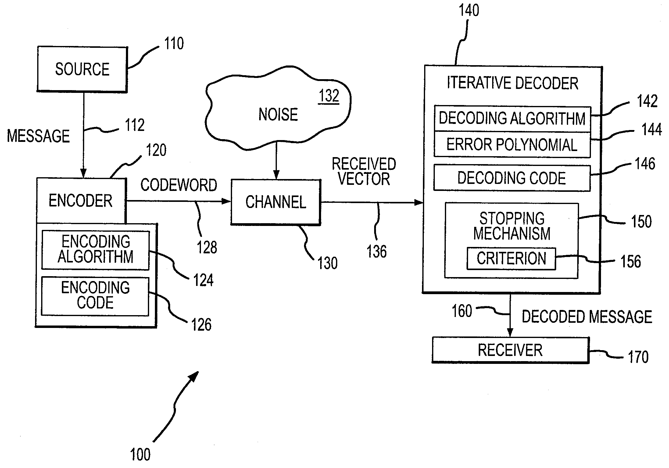
The present invention provides a method and circuitry for error correction in a decoder that can correct errors introduced by noise or interference in a channel. The method involves an iterative loop that operates to correct errors in a message or stream of bits. After a first pass through the loop, a stopping mechanism determines if additional iterations are necessary by comparing an error location polynomial to a threshold. The method significantly reduces the number of iterations required while still obtaining results similar to decoder systems that perform the maximum number of iterations. The decoder includes a decoding and error correction loop that iteratively processes a message that is encoded and transmitted over a communication channel. The encoded message is encoded per a turbo code and the loop includes a decoder configured to run a decoding algorithm that results in production of the error location polynomial. The stopping mechanism obtains the degree of the error location polynomial and compares it to a predetermined threshold to determine whether additional iterations should be performed. The technical effect of the invention is to provide an efficient and effective method for error correction in a decoder that reduces the number of iterations required while still achieving reliable results.

Problems solved by technology

In some embodiments, the encoded message is encoded per a turbo code and the loop includes a decoder configured to run a decoding algorithm which results in production of the error location polynomial.

Method used


Image

  • Iterative decoder with stopping criterion generated from error location polynomial
  • Iterative decoder with stopping criterion generated from error location polynomial
  • Iterative decoder with stopping criterion generated from error location polynomial

Examples


Embodiment Construction

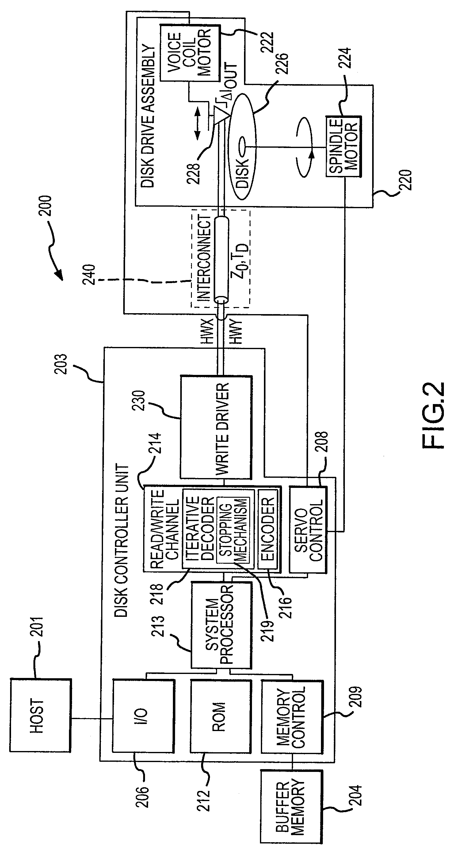
[0019]Briefly, the present invention is directed to an error correction method, and associated circuitry and devices, for use in decoders in communication channels such as read or read / write channel in a hard disk drive (HDD) system. In one embodiment, the inventive method and system uses partial results from an outer Reed-Solomon decoder module in a communication channel (e.g., HDD read channel) decoder to determine if the decoder reiterates a decoding operation. The inventors have determined that a decoder that performs a maximum of 3 decoding iterations only performs on average less than about 1.1 iterations when implementing the stopping criterion of the present invention. Accordingly, only 1 in 10 sectors require 2 iterations and only 1 in 500,000 sectors of a hard disk require 3 iterations. Using a combination of queuing theory and stochastic analysis, a feasible hardware implementation of the iterative error correction method can be provided in a decoder system or device (suc...


PUM


Abstract

A decoder for error correction an encoded message, such as one encoded by a turbo encoder, with reduced iterations due to an improved stopping criterion. The decoder includes an error correction loop that iteratively processes a message that is encoded prior to transmittal over a communication channel. The error correction loop generates, such as with a Reed-Solomon decoder, an error location polynomial in each iterative process. A stopping mechanism in the decoder allows an additional iteration of the message decoding based on the error location polynomial, such as by obtaining the degree of the error location polynomial and comparing it to a threshold. In one example, the threshold is the maximum number of symbol errors correctable by the Reed-Solomon code embodied in the decoder. The stopping mechanism allows additional iterations when the stopping criterion (or polynomial degree) is greater than the maximum number of symbol errors correctable by the Reed-Solomon code.

Description

RELATED APPLICATION[0001]The present application claims priority from, and is a continuation of, U.S. patent application Ser. No. 11 / 257,868 filed on Oct. 25, 2005, now abandoned which is hereby incorporated by reference as if fully set forth herein.BACKGROUND OF THE INVENTION[0002]1. Field of the Invention[0003]The present invention relates, in general, to error correction codes for communication channels such as read channels for hard disk drive (HDD) systems and magneto resistive data storage devices and systems, and, more particularly, to a communication channel with an iterative error correction loop implementing a stopping criterion mechanism that significantly reduces the number of iterations, such as by generating a stopping criterion using the Reed-Solomon error location polynomial that is used to determine whether additional iterations are to be performed.[0004]2. Relevant Background[0005]The demand for improved data storage techniques and systems continues to rapidly grow...

Claims


Application Information

Patent Timeline
Patent Type & Authority Patents(United States)
IPC IPC(8): H03M13/00
CPCH03M13/1525H03M13/2906H03M13/2936H03M13/3753
Inventor LIAO, YUBLISS, WILLIAM G.YEO, ENGLING
Owner STMICROELECTRONICS SRL
Learn More