Automatic take-up device and in-line coupler

a take-up device and take-up coupler technology, applied in the direction of rod connections, washing machines, building repairs, etc., can solve the problems of reducing the service life of the tie-down system, reducing the service life of the device, and reducing the frictional turning resistance of the take-up action of the device. , to achieve the effect of reducing the frictional turning reducing the frictional resistance of the take-up action, and being easy to

Active Publication Date: 2011-03-15
SIMPSON STRONG TIE
View PDF203 Cites 31 Cited by
  • Summary
  • Abstract
  • Description
  • Claims
  • Application Information

AI Technical Summary

Benefits of technology

[0015]The objective of the present invention is to provide an automatic take-up coupler which is relatively small, relatively inexpensive and easy to install.
[0016]Another objective is to provide an automatic take-up coupler which will reliably achieve a selected design tension during a reasonable selected time period in the life of the building.
[0017]A still further objective is to provide an automatic take-up coupler which has reduced frictional turning resistance to the take-up action of the device.

Problems solved by technology

However, a number of different factors can cause the tie-down system to lose its tension.
One such factor is wood shrinkage.
Once the envelope of the building is completed, the lumber is no longer exposed to the relatively humid outside air, and it begins to lose moisture which leads to shrinkage.
Manually turning the turnbuckles or other devices used to re-tension the cables is an expensive proposition particularly where building panels must be removed to reach the turnbuckles or other tightening devices.

Method used


Image

  • Automatic take-up device and in-line coupler
  • Automatic take-up device and in-line coupler
  • Automatic take-up device and in-line coupler

Examples


Embodiment Construction

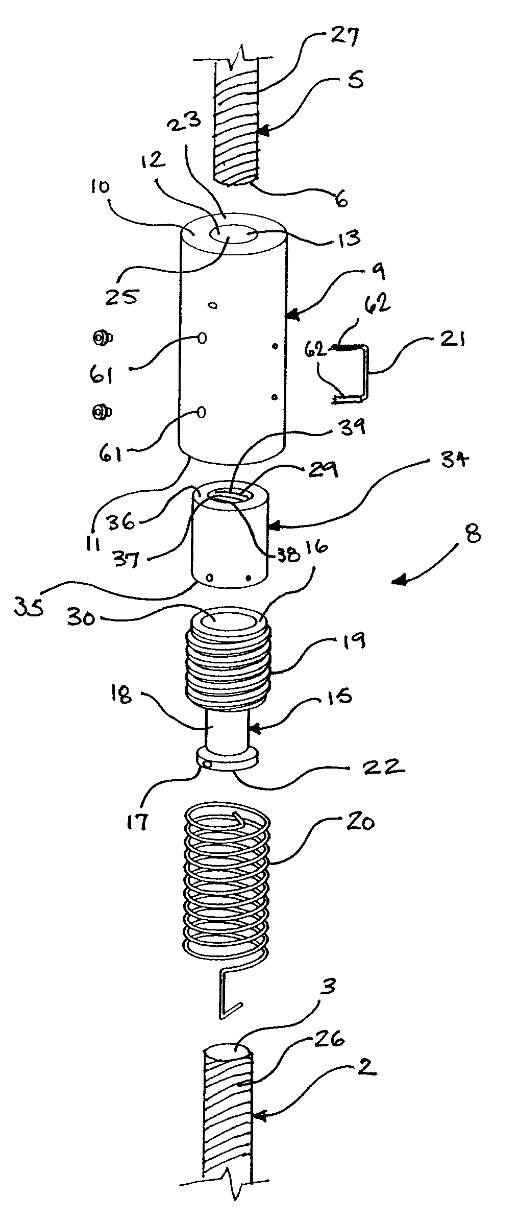
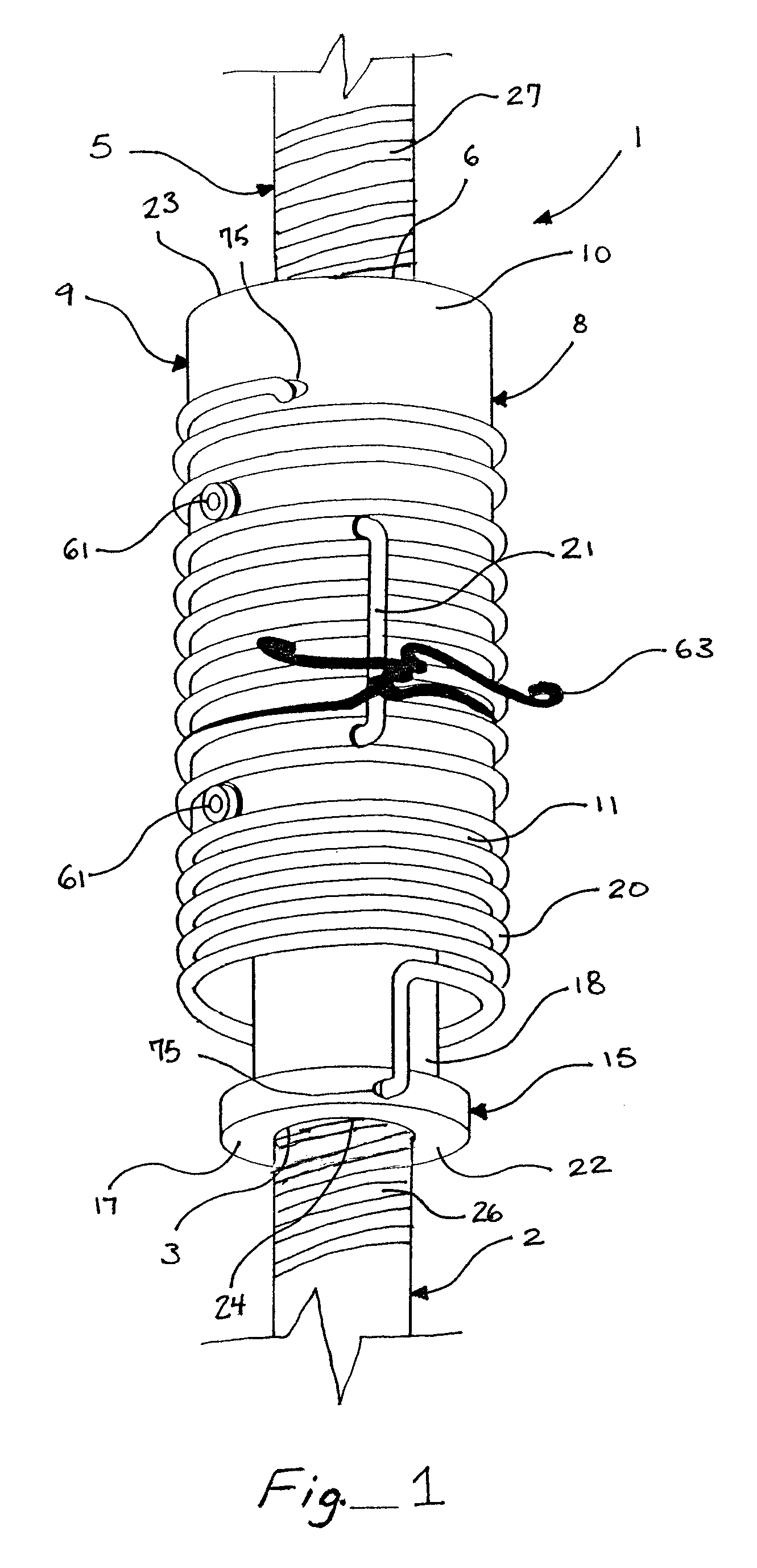
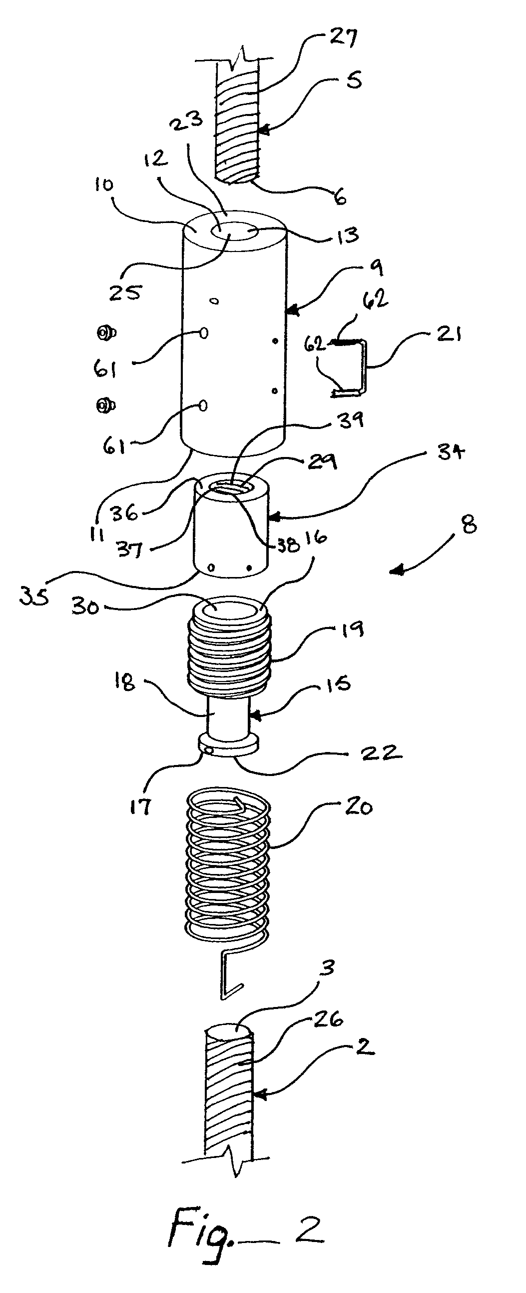
[0039]As shown in FIG. 1, the coupler 8 of the preferred form of the present invention includes a surrounding sleeve 9, a first rotational member 15, and a torsion spring 20. The preferred coupler 8 compensates for wood shrinkage and settlement due to dead load and construction loading, which occur in continuous tiedown systems, and uplift load path systems in wood and steel framed structures. The preferred coupler 8 is an in-line coupling device that compensates for up to one inch of wood shrinkage and settlement from the level above. The coupler 8 connects threaded rods together between storey levels, and maintains a tight configuration when shrinkage or settlement occurs. The preferred device can be installed at any height in the wall. Reducing couplers 8 allow transition between different rod diameters. The coupler 8 is generally not required to lift dead load.

[0040]The torsion spring 20 must have sufficient energy to rotate the surrounding sleeve 9 and the first rotational memb...


PUM


Abstract

A tension connection for a building includes a first tension member, the first tension member being anchored at its distal end, a second tension member being anchored at its distal end; the first and second tension members being disposed in close proximity and connected by a coupler having a surrounding sleeve and a central bore with a thread, the coupler also being formed with a first rotational member being received in the central bore of the surrounding sleeve and operatively connected to the surrounding sleeve; the first rotational member is connected to the surrounding sleeve, such that the rotational member can rotate in relation to the surrounding sleeve. A torsion spring connects the first rotational member and the surrounding sleeve; the torsion spring biasing the first rotational member and the surrounding sleeve in opposite rotational directions such that the first rotational member can be drawn into the surrounding sleeve.

Description

BACKGROUND OF THE INVENTION[0001]The present invention relates to an automatic take-up coupler. The coupler is adapted for maintaining two structural members in tension. The coupler of the present invention is connected to two elongated tension members and is designed to draw the two elongated tension members together where dimensional changes in the structures occur as in shrinkage of the wood materials.[0002]The device is adapted for maintaining the tension forces between a pair of elongated tension members. The present invention is inserted between two elongated tension members and is designed to allow the ends of the two elongated tension members it connects to draw together, if conditions push the two proximal ends closer to each other or tension on the two ends is reduced.[0003]The present invention is particularly suited for use with tie-down systems used to anchor wood-framed buildings to their foundations. Many such systems use a rod or bolt or an in-line series of rods or ...

Claims


Application Information

Patent Timeline
Patent Type & Authority Patents(United States)
IPC IPC(8): E04C5/08F16C11/00F16F1/14F16B43/00E04G23/00E04C3/00E04B1/343
CPCE04B1/26E04C5/165E04B2001/2688E04B2001/3583Y10T403/32541Y10T403/551Y10T403/32827
Inventor PRYOR, STEVEN E.MCGURTY, LISA M.LEEK, WILLIAM F.PROCTOR, RICHARD I.
Owner SIMPSON STRONG TIE
Why Eureka
Try Eureka