Row-insensitive feeding and picking device for an agricultural header

a technology of a picker and a feeding device, which is applied in the direction of metal working equipment, portable power tools, agriculture tools and machines, etc., can solve the problems of large overall length, large width, and inability to grasp the device, and achieve uniform weight distribution, large width, and constant width

Active Publication Date: 2011-03-15
MASCHFAB KEMPER
View PDF41 Cites 5 Cited by
  • Summary
  • Abstract
  • Description
  • Claims
  • Application Information

AI Technical Summary

Benefits of technology

[0023]In lieu of conventional cylindrical snapping rolls, it is also possible to use conical snapping rolls. Two conical snapping rolls can be mounted at a specific angle with respect to each other; thus ensuring that a gap of constant width is maintained between said rollers.
[0024]The feeding and picking device of the present invention is used on crop harvesting machines having a plurality of feeding and picking devices. With crop harvesting machines having a large width, it is useful to provide feeding and picking devices that are symmetrical with respect to each other on both sides of a symmetrical line which generally coincides with the centerline of the crop-harvesting machine. The symmetry makes it possible to uniformly distribute the weight, thus making it possible to avoid undesirable torsional forces on the vehicle to which the crop harvesting machine is attached.
[0025]Although the feeding and picking device is designed to pick corn in fields not planted in rows, it may be useful to mount said device in a substantially known manner to the crop harvesting machine so as to be laterally adjustable. If desired, the snapping bars of adjacently located feeding and picking devices can overlap one another, thus ensuring that no undesirable gaps form when said devices are adjusted. As an alternative or in addition thereto, additional snapping bars between adjacent feeding and picking devices can close potentially remaining gaps.
[0026]And finally, it is also possible to provide adjacent feeding and picking devices that are mounted at different heights so as to reduce the minimum distance between them.

Problems solved by technology

The disadvantage of these prior-art corn pickers is that they are able to grasp only plants that grow in the immediate proximity of the feed channel.
In practice, however, this device proved to be a failure.
The plants are subsequently fed to conventional picker units that are mounted downstream of the mowing unit, such picker units are disclosed in German Patent No. 30 29 424 A. Although this device is able to work in fields not planted in rows, it has the disadvantage that it requires complex technical equipment and has a considerable overall length.
It is conceivable that with respect to the direction of forward travel, the picking device could be mounted behind the feeding device; however, given a straight snapping channel of the picking device, this would mean that the snapping channel could not be sufficiently long or that problems would arise when the plants are conveyed from the feeding device to the picking device since the direction would then necessarily have to be changed.

Method used


Image

  • Row-insensitive feeding and picking device for an agricultural header
  • Row-insensitive feeding and picking device for an agricultural header
  • Row-insensitive feeding and picking device for an agricultural header

Examples


Embodiment Construction

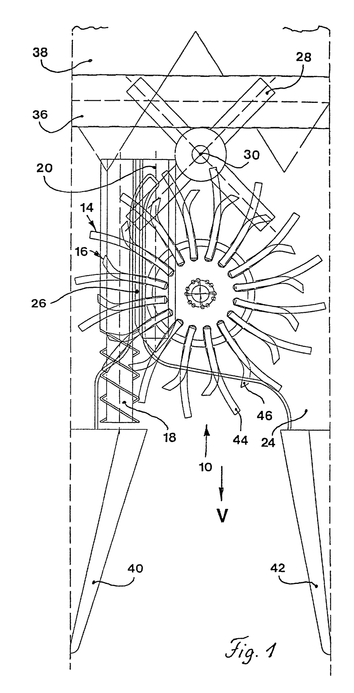
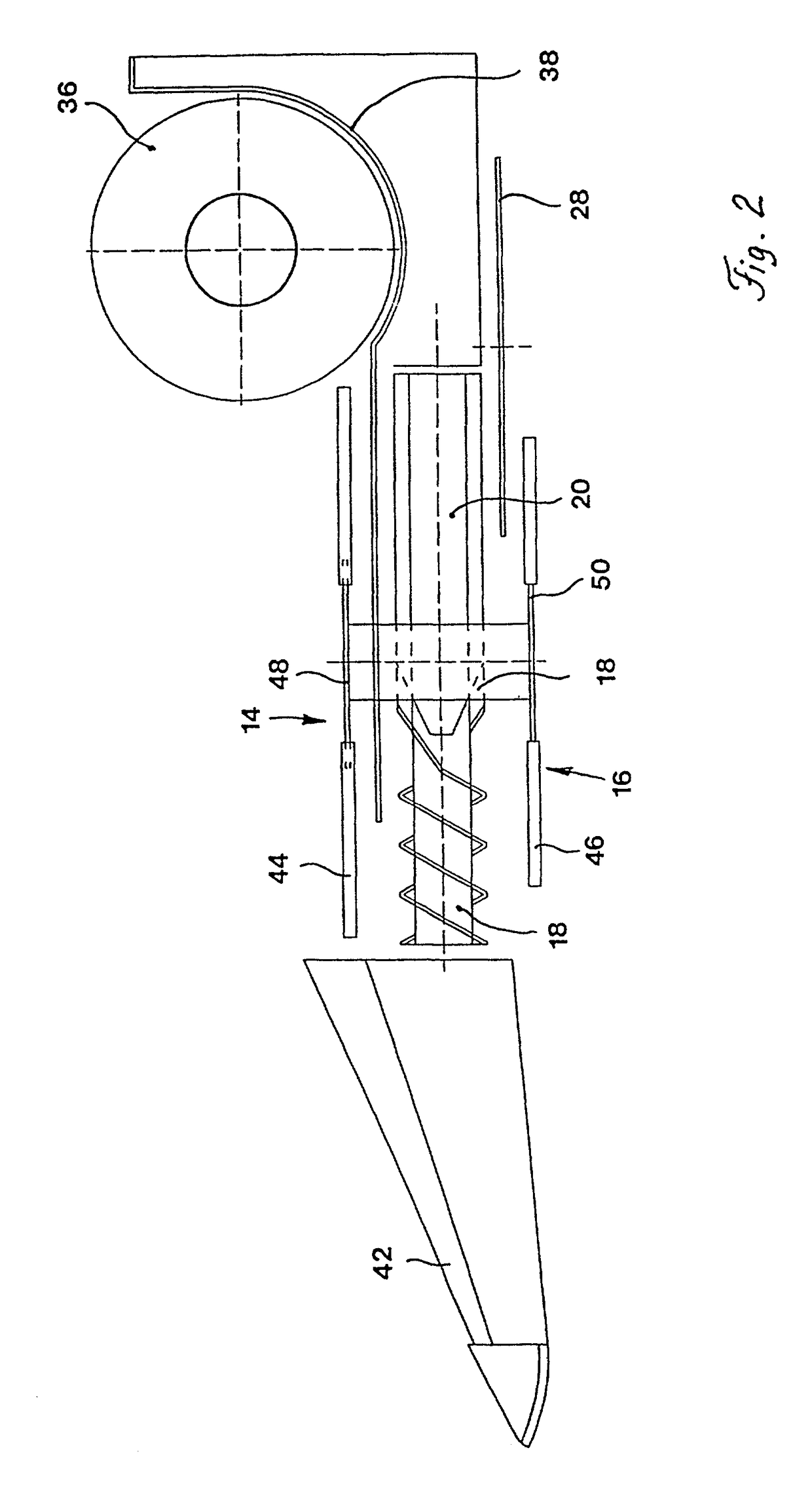
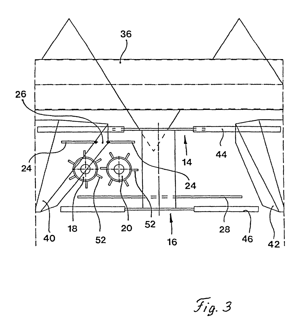
[0040]FIG. 1 illustrates a feeding and picking device 10 of a crop-harvesting machine. Typically, a crop harvesting machine 12, as shown in FIG. 4, comprises a plurality of feeding and picking devices 10; although, a crop harvesting machine 12 may be fitted with a single feeding and picking device 10. The feeding and picking device 10 comprises an upper feeding element 14, a lower feeding element 16, a rotary cutting knife 28, a first snapping roll 18, a second snapping roll 20, and a snapping channel 26 formed by snapping bars 24.

[0041]The upper feeding element 14 and the lower feeding element 16 grasp and draw the plant to be harvested into the crop-harvesting machine 12. These elements 14 and 16 are rotatably mounted on a vertical axis and rotate in the same direction by a drive, not shown. The upper feeding element 14 is mounted above the snapping bar 24, and the lower feeding element 16 is mounted beneath the snapping bar 24. In the illustrated embodiments, the axes of rotation...


PUM


Abstract

A feeding and picking device having a rotating feeding device that is rotated about a vertical axis. The device is able to work in fields not planted in rows and is designed to grasp plant stalks and feed them into a picking device. The picking device comprises a snapping channel formed by snapping bars under which is located at least one snapping roll. The feeding device comprises a disc having fingers that overlap the snapping channel. The feeding device is therefore designed to transport the plant throughout the effective length of the picking device.

Description

BACKGROUND OF THE INVENTION[0001]1. Field of the Invention[0002]The present invention is directed to a feeding and picking device for an agricultural crop having a feeding element that has a vertical axis of rotation.[0003]2. Description of the Prior Art[0004]A corn picker disclosed in German Patent No. 30 29 424 A comprises a plurality of gathering snouts that define a plurality of feed channels. Each of the feed channels is provided with longitudinally extending gathering chains that overlie snapping bars defining a snapping gap. Two snapping rolls underlie the snapping bars. The plant stalks are grasped and drawn in by horizontal counterrotating snapping rolls. The snapping gap snaps ears of corn from the stalks. The gathering chains then transport the ears of corn to a screw conveyer. The plant stalks, on the other hand, are completely drawn in by the snapping rolls and deposited on the ground of the field. In many corn pickers, the plant stalks are chopped into pieces by a knif...

Claims


Application Information

Patent Timeline
Patent Type & Authority Patents(United States)
IPC IPC(8): A01D45/02
CPCA01D45/021
Inventor WOLTERS, NORBERTWUBBELS, RICHARD
Owner MASCHFAB KEMPER
Why Eureka
Try Eureka