Marine muffler with angularly disposed internal baffle

a technology of internal baffles and mufflers, which is applied in the direction of mechanical equipment, pipes, machines/engines, etc., can solve the problems of significant space limitations, reduced or very limited space availability of propulsion system components such as muffler systems, and achieves improved silencing and backpressure characteristics, improved exhaust flow dynamics, and easy manufacturing and installation

Active Publication Date: 2011-03-15
WOODS WOODROW
View PDF51 Cites 21 Cited by
  • Summary
  • Abstract
  • Description
  • Claims
  • Application Information

AI Technical Summary

Benefits of technology

[0011]The present invention overcomes limitations present in the art by providing an improved muffler for marine engines that is compact, and provides improved performance in terms of silencing and backpressure characteristics, as well as ease of manufacturing and installation. A marine muffler comprises an elongate housing having an inlet and an outlet and defining an internal volume. The internal volume is partitioned into upper and lower chambers by an angularly disposed internal baffle, with the lower chamber in communication with the inlet and the upper chamber in communication with the outlet. The baffle is adapted with at least one vertically disposed duct to allow exhaust gas and exhaust cooling water to flow from the lower inlet chamber to upper outlet chamber. The exhaust duct may preferably be further adapted with internal structure forming a plurality of individual non-circular flow conduits or passages. The duct is preferably positioned such that a plurality of flow passage inlets are disposed in proximity to the lower housing wall, with flow passage outlets positioned in proximity to the upper housing wall. The lower duct walls may further be adapted with sidewall apertures for improving exhaust flow dynamics through the duct. Structure is provided to provide rigidity in embodiments that use muffler housings having rectangular cross-sections and / or planar surfaces.
[0016]Yet another object of the present invention is to provide such a muffler the lower duct wall defines a plurality of apertures to improve water entrainment.

Problems solved by technology

Current trends in marine vessel design, however, have resulted in reduced or very limited space availability for propulsion system components such as muffler systems.
In addition, space limitations present in the retrofit and re-powering of existing marine vessels often present significant space limitations relating to the replacement of muffler systems.

Method used


Image

  • Marine muffler with angularly disposed internal baffle
  • Marine muffler with angularly disposed internal baffle
  • Marine muffler with angularly disposed internal baffle

Examples


Embodiment Construction

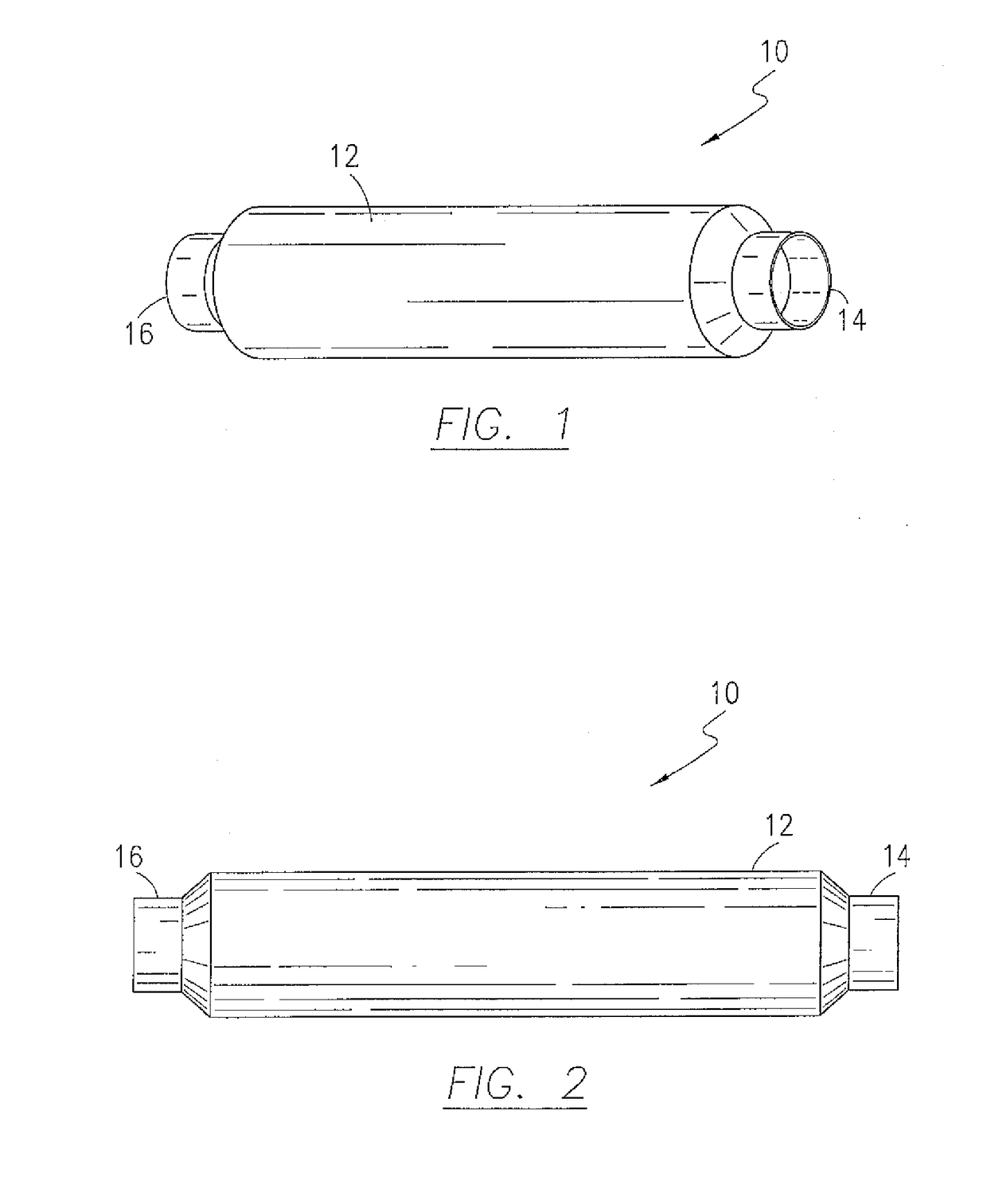
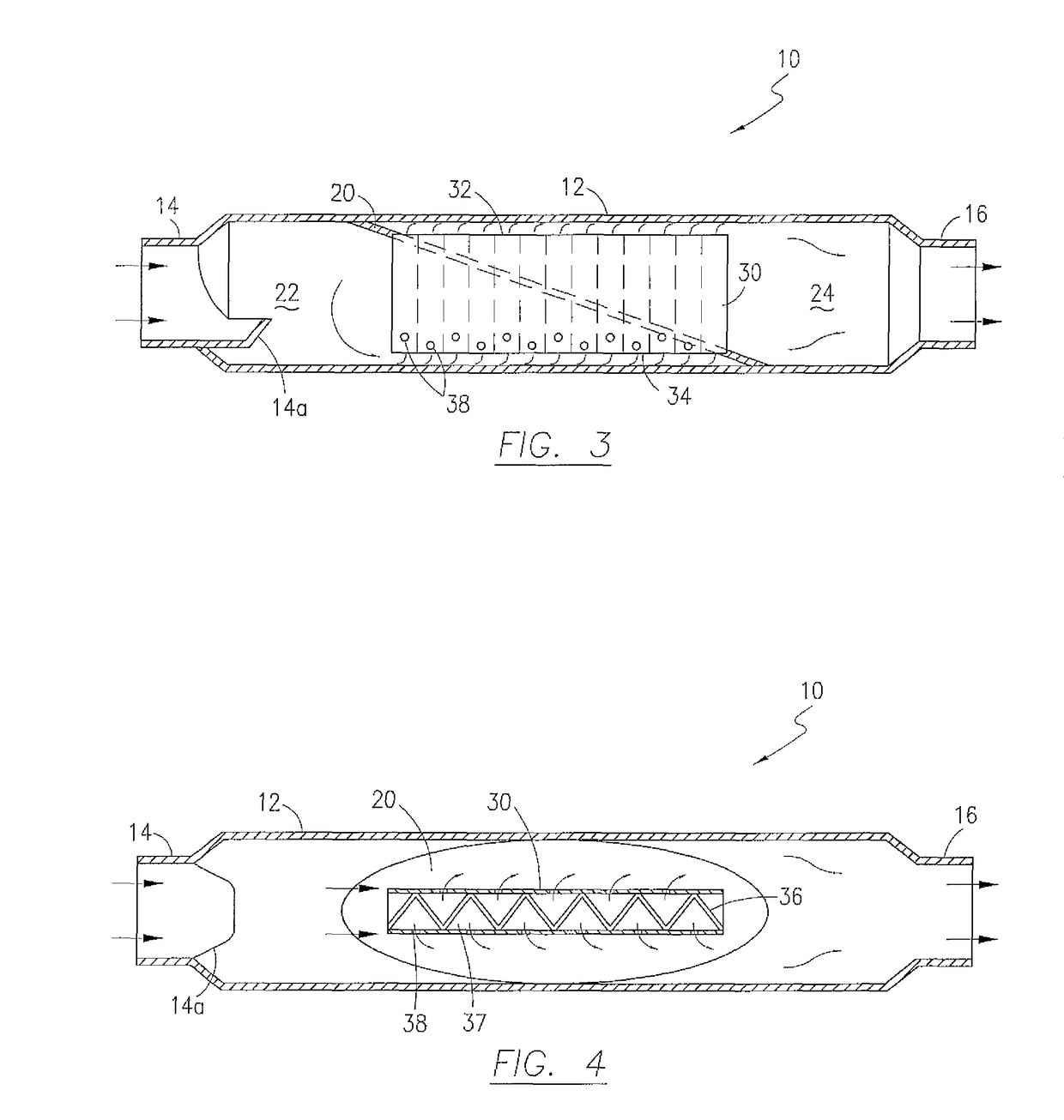
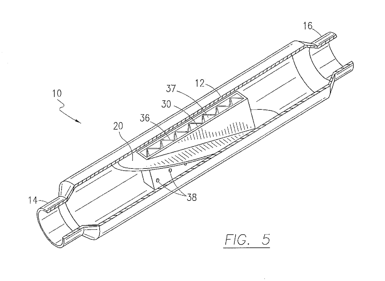
[0030]With reference now to the drawings, FIGS. 1-5 depict a preferred embodiment of a muffler, generally referenced as 10, in accordance with the present invention. Muffler 10 is primarily characterized as having an elongate generally hollow muffler housing 12 formed about a longitudinal axis with opposing ends forming an open inlet 14 and an open outlet 16. In a preferred embodiment, housing 12 comprises a generally cylindrical structure fabricated from composite material such as temperature resistant fiberglass. While the preferred embodiment is disclosed with a housing that is generally cylindrical, the present invention is suitable for use with housings having various shapes. As best depicted in FIG. 3, muffler housing 12 defines an internal volume and includes an angularly disposed baffle 20, having a peripheral edge in sealing engagement with the inner surface of housing 12, which divides the internal volume into a lower inlet chamber 22 and an upper outlet chamber 24. In a p...


PUM


Abstract

A marine muffler comprises an elongate cylindrical housing having an inlet and an outlet and defining an internal volume partitioned, by an angularly disposed internal baffle, into a lower chamber in communication with the inlet and an upper chamber in communication with the outlet. A vertically disposed duct is insertably secured to the baffle to allow exhaust gas and exhaust cooling water to flow from the lower inlet chamber to upper outlet chamber. The exhaust duct may preferably be further adapted with internal structure forming a plurality of individual flow conduits or passages. The duct is preferably positioned such that a plurality of flow passage inlets are positioned in proximity to the lower cylindrical housing wall, with flow passage outlets positioned in proximity to the upper housing wall. The lower duct wall may further be adapted with sidewall apertures for improving exhaust flow dynamics therethrough.

Description

CROSS REFERENCE TO RELATED APPLICATIONS[0001]This application is a continuation in part of U.S. patent application Ser. No. 12 / 548,548, filed on Aug. 27, 2009, which is a continuation of U.S. patent application Ser. No. 11 / 891,481, filed Aug. 10, 2007, now U.S. Pat. No. 7,581,620, which claims the benefit of provisional U.S. Patent Application No. 60 / 837,350, filed Aug. 10, 2006.STATEMENT REGARDING FEDERALLY SPONSORED RESEARCH OR DEVELOPMENTN / ACOPYRIGHT NOTICE[0002]A portion of the disclosure of this patent document contains material that is subject to copyright protection. The copyright owner has no objection to the facsimile reproduction by anyone of the patent document or patent disclosure as it appears in the Patent and Trademark Office patent file or records, but otherwise reserves all copyrights rights whatsoever.BACKGROUND OF THE INVENTION[0003]1. Field of the Invention[0004]The present invention relates generally to exhaust systems and mufflers for use with internal combusti...

Claims


Application Information

Patent Timeline
Patent Type & Authority Patents(United States)
IPC IPC(8): F01N1/08F01N1/02F01N1/00
CPCF01N1/08F01N13/004
Inventor WOODS, WOODROWWOODS, DARRINMCLEOD, CRAIG
Owner WOODS WOODROW
Why Eureka
Try Eureka