Method and devices for installing packet filters in a data transmission

a packet filter and data transmission technology, applied in data switching networks, instruments, frequency-division multiplexes, etc., can solve the problems of inflexible existing methods for associating data packets with bearers, inability to dynamically change configuration, and not in the scope of current 3gpp standards. achieve the effect of simple and flexibl

Active Publication Date: 2011-03-15
TELEFON AB LM ERICSSON (PUBL)
View PDF5 Cites 26 Cited by
  • Summary
  • Abstract
  • Description
  • Claims
  • Application Information

AI Technical Summary

Benefits of technology

With this background, it is an object of the present invention to propose a simple and flexible method for associating data packets with a bearer in a user equipment of a communication network.
The proposed method allows a simple and flexible association of data packets to packet bearers which does not require a prior configuration of the association and can be established before, at or after the initiation of a data session. The proposed method provides a controlled way for the communication network, i.e., the operator of the network, for mapping data packets onto bearers in the uplink from the user equipment to a further entity and thus to provide differentiation between services and between users. The network can allow or forbid the mapping of selected flows to bearers in the user equipment by the policy function controlling the filter installation. For this purpose, the operator may specify policy rules. In addition, the method enables access agnostic application development, i.e., applications can be developed independently of the access network to which the user equipment is connected because only ubiquitous socket API functions are used. This simplifies the development of applications making the development less expensive. The routing level identification can be set by the application through the socket API. The method does not introduce new dedicated signals to install the uplink packet filter but reuses existing procedures for this purpose and can accordingly easily be implemented in existing communication networks.
In an advantageous embodiment of the proposed method, an establishment of a communication session is initiated between the user equipment and the further entity by an initiation message. The initiation message comprises a session level identification of the further entity, e.g., in the format of a telephone number, a uniform resource locator (URL) or an e-mail address or any other session level identification. A monitoring entity is adapted to monitor messages sent between the user equipment and the further entity for establishing the session. The monitoring entity stores information related to the communication session. For example, the monitoring entity can be a call state control function storing a state for initiated sessions. The monitoring entity may be associated with an entity for performing an address resolution of the session level identification for forwarding the initiation message to the further entity. The initiation message is forwarded towards the further entity using the session level identification. The monitoring entity then waits for a reply message related to the establishment of the communication session and determines the routing level identification of the further entity from the reply message. It is possible to receive several reply messages and the routing level identification can be determined from one or several reply messages. The reply message is forwarded to the user equipment and the session establishment is completed. This embodiment allows a simple implementation to obtain the required information and to determine the identification of the flow, especially for the originating side of the session.
In an alternative embodiment of the proposed method, an establishment of a communication session between the further entity and the user equipment is initiated by an initiation message comprising a routing level identification of the further entity and a session level identification of the user equipment. A monitoring entity is adapted to receive the initiation message and to determine the routing level identification of the further entity from the initiation message. The initiation message is then forwarded towards the user equipment using the session level identification, and the session establishment is completed. This embodiment allows a simple implementation to obtain the required information and to determine the identification of the flow, especially for the terminating side of the session.
In an advantageous embodiment, the setup of the packet bearer is initiated by a request from a node in the communication network. This allows an improved control of the network operator over the transmission by the user equipment.
In a preferable embodiment, the data packet is an internet protocol IP data packet. This allows an easy implementation of the method in existing networks. Session initiation signaling can be performed using a session protocol which is based on the IP protocol. Suitable protocols are for example the session initiation protocol (SIP) or the real time streaming protocol (RTSP). Both can be used in conjunction with the session description protocol (SDP).

Problems solved by technology

However, this functionality is not in the scope of the current 3GPP standards.
As a result, the existing methods for associating data packets with a bearer are inflexible and do not allow dynamic changes of the configuration.
A further problem is that application development is both access specific and vendor specific, i.e. applications must be written for a specific access (e.g. 3GPP) and a particular vendor of user equipment because the QoS API in the above binding mechanism may differ for both vendor and access.
If the terminal equipment is for example a personal computer and the mobile terminal is a mobile network card, the computer may need to support different interfaces for different card vendors, leading to high complexity and cost.

Method used


Image

  • Method and devices for installing packet filters in a data transmission
  • Method and devices for installing packet filters in a data transmission
  • Method and devices for installing packet filters in a data transmission

Examples


Embodiment Construction

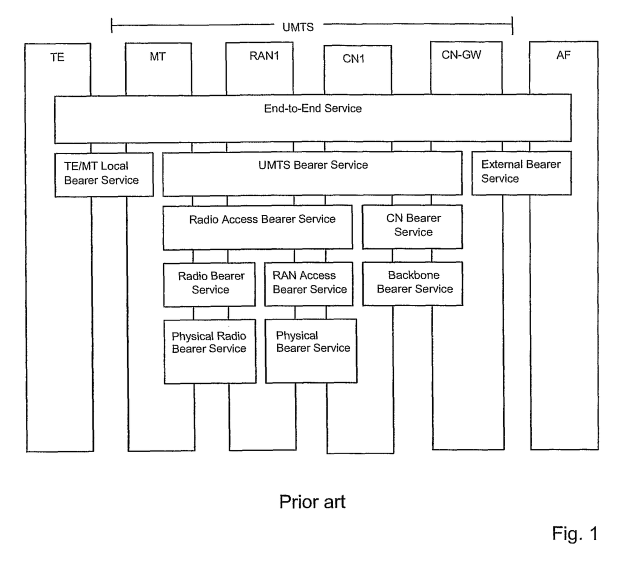
FIG. 1 illustrates a quality of service concept in 3rd generation mobile systems as specified in technical specification 3GPP 23.107 V 6.3.0. of the 3rd Generation Partnership Project. Traffic comprising data packets is sent between a further entity (AF) and a user equipment comprising a terminal equipment (TE) and a mobile terminal (MT). The further entity (AF) may be a server which could be located in the operator's network or in an external network but it can be also another user equipment. The object of the concept is to provide a defined quality of service (QoS) on the application level using the bearer services of the underlying levels. Those bearer services are specified by contexts comprising attributes for defining the QoS of the respective bearer service. As the quality of the end-to-end service on the application layer depends on the specifications of the underlying levels, the contexts of the bearer services need to be specified with respect to the required end-to-end qu...


PUM


Abstract

A method is described for associating a data packet (DP) with a packet bearer (PB) in a user equipment (UE1) of a communication network. The data packet is sent in a data flow from an application function of the user equipment, the packet bearer (PB) is established with the user equipment to transmit the data packet (DP) over the communication network towards a further entity, and the user equipment is adapted to establish different packet bearers. The method comprises the steps of identifying the flow with the data packet in a control entity of the communication network, determining the packet bearer for association with said flow from the different packet bearers in a policy function of the control entity, determining a routing level identification of the further entity, instructing the user equipment to install a packet filter based on the routing level identification, wherein the packet filter associates data packets comprising the routing level identification of the further entity with the determined packet bearer, providing the routing level identification to the application function, including the routing level identification into the data packet, and forwarding the data packet (DP) on the determined packet bearer (PB). A corresponding network, control entity, monitoring entity and computer program are also described.

Description

TECHNICAL FIELD OF THE INVENTIONThe present invention relates to a method for associating a data packet with a packet bearer in a user equipment of a communication network. Devices and software programs embodying the invention are also described.BACKGROUND OF THE INVENTIONIn many cases, data packets need to be sent over a communication network between a user equipment and a further entity. Transmissions can be performed both in downlink and uplink direction and the further entity is often another user equipment, e.g. in a telephone call. The further entity may also be a service entity like a server which may send different packet flows for sound and video to the user equipment, e.g. in a streaming session, while the user equipment may also send packets to the further entity. The further entity can either be part of the communication network or it is able to exchange data packets with the network.The communication network can be a fixed or a mobile network. More than one network can ...

Claims


Application Information

Patent Timeline
Patent Type & Authority Patents(United States)
IPC IPC(8): H04J1/16H04L12/54H04W28/18H04L45/74H04W76/02H04W76/04H04W80/04
CPCH04L12/5695H04L47/803H04L47/808H04L47/824H04W28/18H04L47/825H04W80/04H04W76/02H04W76/04H04L47/70H04W76/20H04W76/10H04L45/745H04L45/38
Inventor WILLARS, PERLUDWIG, REINEREKSTROM, HANNESBASILIER, HENRIK
Owner TELEFON AB LM ERICSSON (PUBL)
Why Eureka
Try Eureka