System and method for marking body cavities

a system and cavity technology, applied in the field of system and method for marking body cavities, can solve the problems of increasing risk and/or discomfort for patients, and it is difficult for surgeons to know with any certainty whether a given calyx has or has not been inspected

Inactive Publication Date: 2011-03-15
CR BARD INC
View PDF19 Cites 6 Cited by
  • Summary
  • Abstract
  • Description
  • Claims
  • Application Information

AI Technical Summary

Problems solved by technology

Because there may be many different calices 16 to inspect and because the position of the viewing device can only be inferentially determined from the images captured by the viewing device and any captured fluoroscopic images, it is often difficult for the surgeon to know with any certainty whether a given calyx has or has not been inspected.
This “double-checking” lengthens the time required to complete the procedure, thereby increasing risk and / or discomfort to the patient.

Method used


Image

  • System and method for marking body cavities
  • System and method for marking body cavities
  • System and method for marking body cavities

Examples


Embodiment Construction

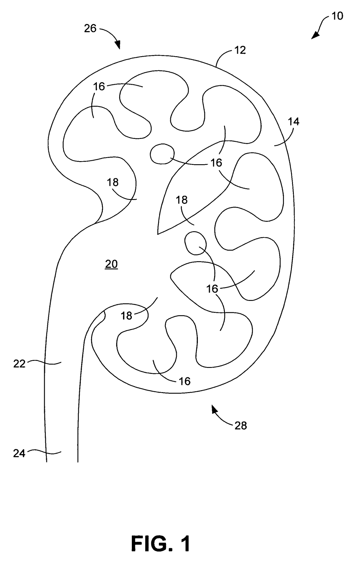
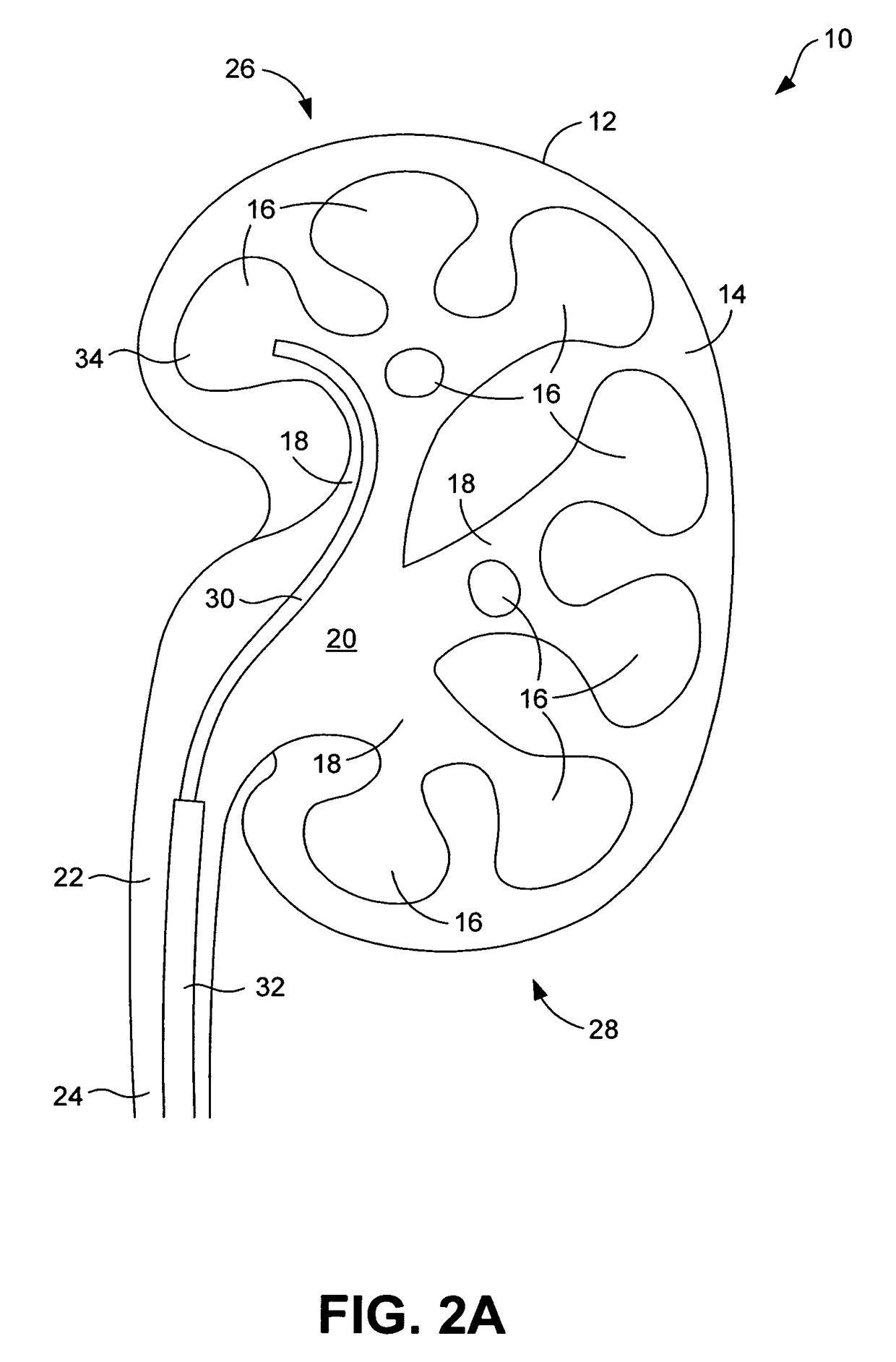
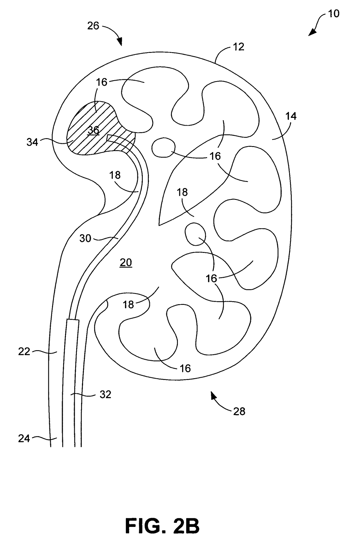
[0021]As is described in the foregoing, it can be difficult to keep track of which of multiple body cavities have or have not been inspected during a surgical procedure. As is discussed in the following, however, the progress of such inspection can be clearly indicated using a marking material. By way of example, such a marking material can be used to mark one or more cavities that have already been inspected. Alternatively, a marking material can be used to mark one or more cavities of interest, for example that contain an object to be removed. In a further alternative, a first type of marking material can be used to mark cavities of a first type (e.g., that contain objects to be removed) and a second type of marking material can be used to mark cavities of a second type (e.g., that contain no objects to be removed). The marking material contains a marking substance that can be viewed with a viewing device and / or that can be viewed fluoroscopically. In the former case, the marking ...


PUM


Abstract

Systems and methods for marking a body cavity. In one embodiment, a system includes means for inspecting a body cavity, and means for visibly marking the body cavity so as to convey visual information regarding the body cavity. In one embodiment, a method includes inspecting a body cavity and marking the body cavity with a marking material to provide a visual indication regarding the cavity. In one embodiment, a marking material for marking a body cavity includes a radiopaque contrast agent that is viewable through fluoroscopy and a colored dye that is viewable using an internal viewing device.

Description

BACKGROUND[0001]Surgeons are often called upon to inspect internal body cavities to diagnose or remedy a medical condition. For example, a surgeon may inspect the calices of a patient's kidney to search for and remove kidney stones.[0002]In the case of kidney inspection and stone removal, the surgeon may need to inspect each of multiple calices of the kidney. FIG. 1 illustrates a typical kidney 10 that is representative of a kidney that a surgeon may need to inspect. As is shown in FIG. 1, the kidney 10 includes an outer capsule 12 that surrounds a renal cortex 14 in which a plurality of minor calices 16 are formed. Each of the minor calices 16 may extend from a major calyx 18 that, in turn, extends from the renal pelvis 20. The renal pelvis 20 is connected to the ureteropelvic junction 22, which leads down to the ureter 24.[0003]To inspect the kidney 10, the surgeon will normally insert a viewing device, such as an endoscope, into each of the calices 16 of the kidney 10 to enable v...

Claims


Application Information

Patent Timeline
Patent Type & Authority Patents(United States)
IPC IPC(8): A61M25/00A61B6/00A61B5/05
CPCA61B19/54A61B2019/5437A61B90/39A61B2090/3937
Inventor KNAPP, TRACEY E.
Owner CR BARD INC
Why Eureka
Try Eureka