System, program products, and methods for controlling drilling fluid parameters

a technology of drilling fluid and program products, applied in the field of well drilling, can solve the problems of increasing environmental and technical risks, increasing the difficulty of proper well control, and yet more critical, and achieve the effect of improving the control of drilling fluid pressure and other parameters

Inactive Publication Date: 2011-03-15
BOARD OF RGT THE UNIV OF TEXAS SYST
View PDF6 Cites 35 Cited by
  • Summary
  • Abstract
  • Description
  • Claims
  • Application Information

AI Technical Summary

Benefits of technology

[0017]In view of the foregoing, embodiments of the present invention provide systems, program products, and methods to enhance the controlling of drilling fluid pressures and other parameters such as in an oil or gas well. Embodiments of systems, program products, and methods for controlling drilling pressures of the present invention, for example, advantageously provide dynamic density control (DDC) and dynamic mud weight windows (DMWW). These embodiments having DDC provide highly adaptive, real-time, process control and can be scalable to any rig, large or small, on land or water. Embodiments of systems, program products, and methods also advantageously allow combined static and dynamic stresses and displacements to be determined continuously at strategic locations in and around the wellbore so that insitu and operationally induced pressure window limitations at specific weal-points are controlled. By coupling feedback loops and high-rate, high-quality, time-lapse data logging, for example, embodiments of the present invention allow an operator / service company team to “walk-the-line” or even “move-the-line”.
[0018]For example, mass and energy balances for an active system account for time-varying bulk volumes, stresses, pressures, fluids, and temperatures, coupled and associated with flows, displacement or movement. On or off switching circuitry can activate individual system element quantifiers in isolation or coupled with other elements to allow selected usage, maximum usage, or no usage of the enhanced system features. An embodiment of a method of controlling drilling fluid pressures includes monitoring the fluid pressure in real-time and increasing fluid head pressure within a drill pipe and annulus of a well to thereby control downhole pressures within pre-selected limits.
[0019]Additionally, many applications for embodiments of systems, program products, and methods of the present invention abound. For example, applications can include detecting pressure changes where critical pressure magnitudes and small pressure tolerances have large economic, technical, safety, and environmental consequences; in distinguishing between kicking flow and ballooning flow in kick / loss scenarios; in minimizing formation damage during drilling / completion operations; in identifying likely trouble spots in advance; and in training, predictive, what-ifs, and case studies.
[0023]Advantageously, embodiments of the present invention provide a system, program product, and methods that can monitor and control pressure, volume, density, temperature, fluid composition, molecular concentration of both single phase and multiphase drilling fluid both when entering and when exiting the drilling circulation system and at any location from the surface and along the length inside the drilling string and in the annulus, i.e., either side of the U-tube, at any time or operational drilling phase. The system, program product, and methods advantageously can account for the pressure changes and other factors inside the drilling string, in the annulus, at the choke, at the bottom of the hole, and can account for the volume of drilling fluid required to pressurize the circulation system. The system, program product, and methods can measure compressibility of associated rocks, fluid in the rocks, cement in the hole, the casing strings cemented in the hole, the drilling fluid, the drilling string assembly to formulate a running description of the physical behavior of the drilling system and all components, and can account for such compressibility to thereby enhance dynamic density control throughout the system. Further, the system, program product, and methods advantageously can account for friction losses for any location for any rheology and physical dimensions of the circulation system, and can determine and compensate for the existence of mud channels in the drilling string cement. Such system, program product, and methods can dynamically manipulate the mud weight window, and can predict maximum dynamic bottom hole pressure at future depths to be drilled to thereby anticipate future drilling requirements to drill at the future depth including a requirement to order supplies, people, third party services, etc. Embodiments of the present invention can utilize surface parameters, e.g., flow rates, pressures, densities, fluid compositions (in and out); system parameters, e.g., flow rates, pressures, densities, friction losses, temperature distributions of the drilling fluid, to predict operational parameters of the drilling fluid to thereby control drilling fluid parameters. Additionally, embodiments of the present invention can utilize gas volume and solubility profiles in system, and can determine fracture volumes with pressure-volume-time curves / solubility data for the drilling fluids determined by testing or in real-time during operations. Embodiments of the present invention can also incorporate compressibility and load / displacement rules or qualifications (all elements) and strategic space and time derivatives to enhance control.

Problems solved by technology

More and more oil exploration is moving toward ever challenging environments, which present increasing environmental and technical risks.
As well drilling operations reach into deeper and deeper depths, proper well control becomes ever more challenging and yet more critical.
Further, and deeper depths, some formations may not tolerate significant variations in hydrostatic pressure.
This methodology is extremely inefficient as hours may pass as the weighing agent is being added to the drilling fluid and circulated through the circulation system.
Previously employed methodologies do not account for the compressibility of associated rocks, fluid in the rocks, cement in the hole, the casing strings cemented in the hole, the drilling fluid, the drilling string assembly when drilling, which is an enormous volume of material.

Method used


Image

  • System, program products, and methods for controlling drilling fluid parameters
  • System, program products, and methods for controlling drilling fluid parameters
  • System, program products, and methods for controlling drilling fluid parameters

Examples


Embodiment Construction

[0036]The present invention now will be described more fully hereinafter with reference to the accompanying drawings in which embodiments of the invention are shown. This invention, however, may be embodied in many different forms and should not be construed as limited to the embodiments set forth herein; rather, these embodiments are provided so that this disclosure will be thorough and complete, and will fully convey the scope of the invention to those skilled in the art. Like numbers refer to like elements throughout, and prime or double prime notation where used in association with numbers indicates like elements in alternative embodiments.

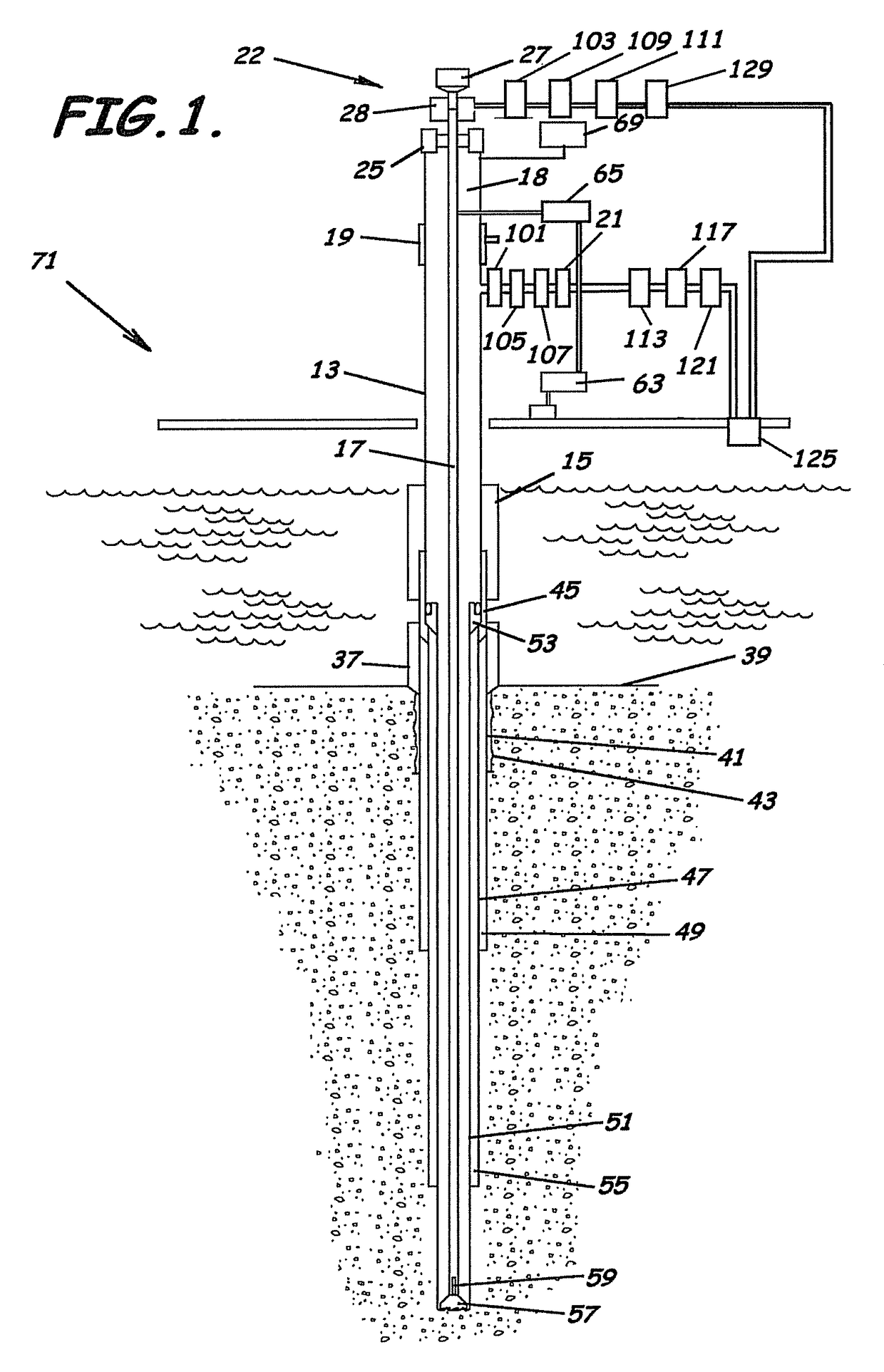
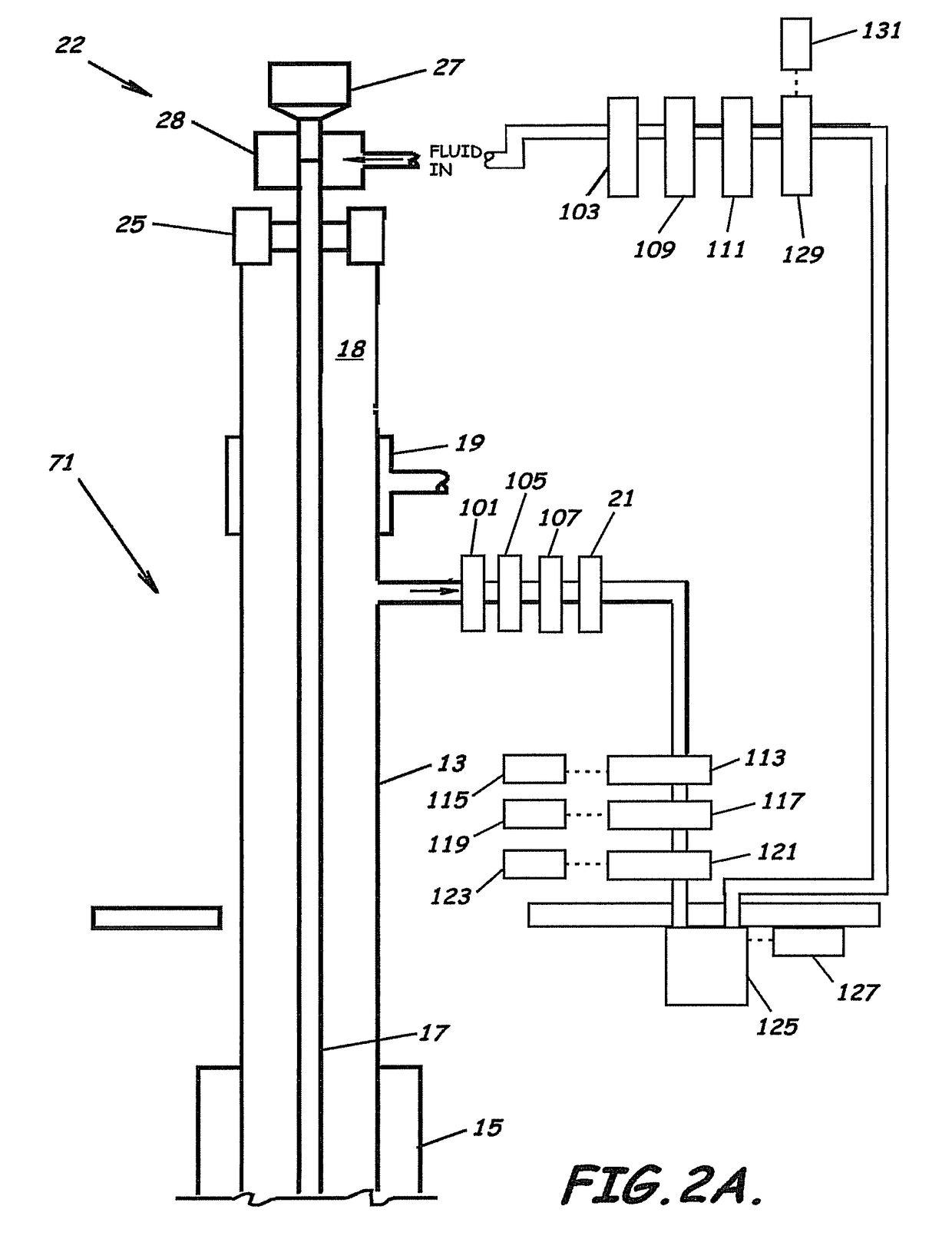
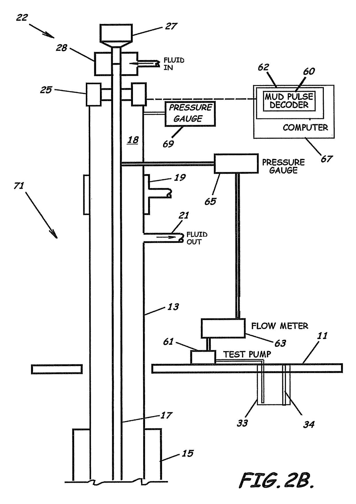
[0037]FIGS. 1 and 2A-2C, the method of this invention illustrate embodiments of a system 22 and method of the present invention in connection with an offshore platform 11. The invention, however, is also applicable to land well drilling operations. The equipment utilized for drilling offshore well 71 in accordance with this embodiment of a sys...


PUM


Abstract

Embodiments of systems, program products, and methods for controlling drilling fluid parameters are provided. These embodiments, for example, provide dynamic density control with highly adaptive, real-time, process-control and are scalable to any rig, large or small, on land or water. Combined static and dynamic stresses and displacements can be determined continuously at strategic locations in and around the wellbore of a well so that insitu and operational induced pressure window limitations at specific weak-points or other locations of interest are controlled.

Description

RELATED APPLICATION[0001]This application claims priority to PCT Application PCT / US2006 / 025964, International Filing date Jun. 30, 2006 which claims priority to U.S. patent application No. 60 / 696,092, filed Jul. 1, 2005 and U.S. patent application No. 60 / 701,744, filed Jul. 23, 2005.BACKGROUND OF THE INVENTION[0002]1. Field of the Invention[0003]This invention relates in general to well drilling and, in particular, to systems, program products, and methods associated with controlling drilling-fluid parameters in an oil or gas well.[0004]2. Description of the Related Art[0005]More and more oil exploration is moving toward ever challenging environments, which present increasing environmental and technical risks. Such environments are resulting in narrow or margins between the pressure of fluids inside the pores of rock at the bottom of a well hole, known as pore pressure, and the pressure which causes a rock formation containing or adjacent a formation containing desired hydrocarbons ...

Claims


Application Information

Patent Timeline
Patent Type & Authority Patents(United States)
IPC IPC(8): G05D7/00G05D11/00
CPCE21B21/00E21B47/10E21B21/08E21B47/117E21B21/062
Inventor GRAY, KENNETH E.
Owner BOARD OF RGT THE UNIV OF TEXAS SYST
Why Eureka
Try Eureka