Self-leveling laser horizon for navigation guidance

a laser horizon and self-leveling technology, applied in the direction of navigation instruments, process and machine control, instruments, etc., can solve the problems of difficult to see, device drawbacks, and limited size of horizon devices

Inactive Publication Date: 2011-03-15
MUNRO & ASSOCS
View PDF146 Cites 14 Cited by
  • Summary
  • Abstract
  • Description
  • Claims
  • Application Information

AI Technical Summary

Problems solved by technology

However, these devices have drawbacks.
Given the space constraints on the control panel, horizon devices have been limited in size; often no more than a few inches across.
The limited size makes them difficult to see and requires that the pilot focus directly on the horizon device to obtain visual information.
These types of devices are limited in that they do not provide an output that may be used by secondary devices in the vehicle.
Combination devices strapped down to the vehicle, including accelerometers and gyroscopes, utilize complicated algorithms to de-convolute the cross-correlated sensor signals that result from such a device.
Artificial horizons have also been cost prohibitive for wide adoption.

Method used


Image

  • Self-leveling laser horizon for navigation guidance
  • Self-leveling laser horizon for navigation guidance
  • Self-leveling laser horizon for navigation guidance

Examples


Embodiment Construction

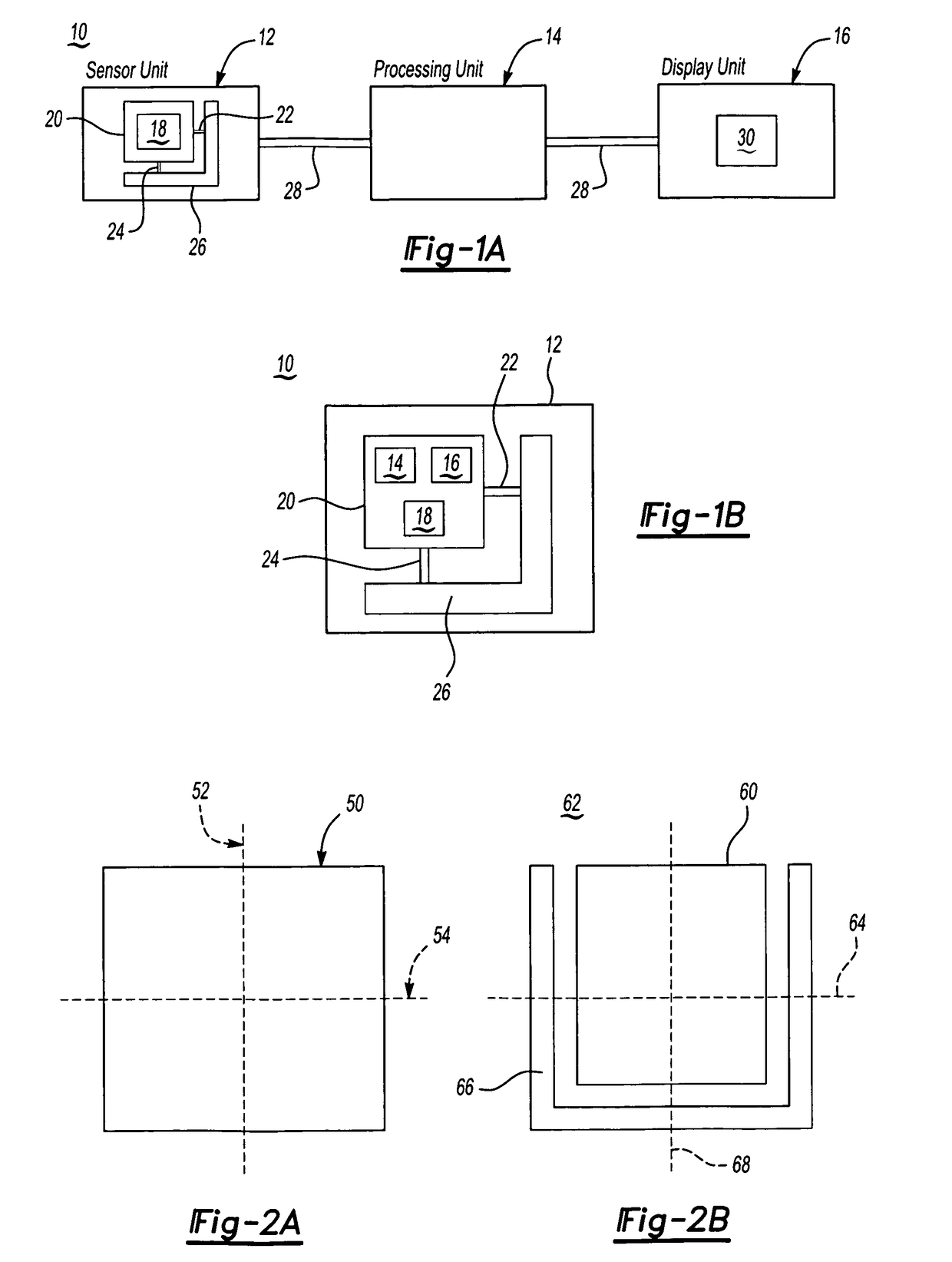
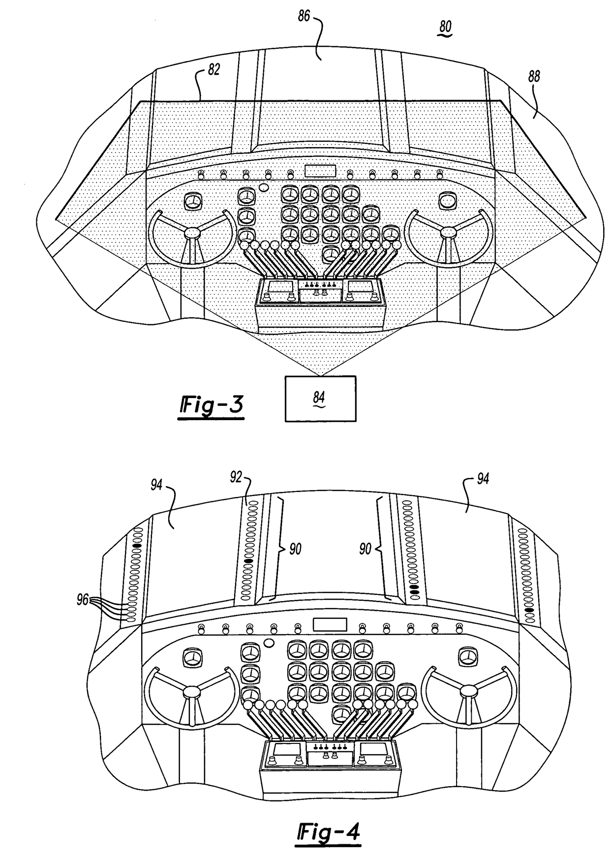
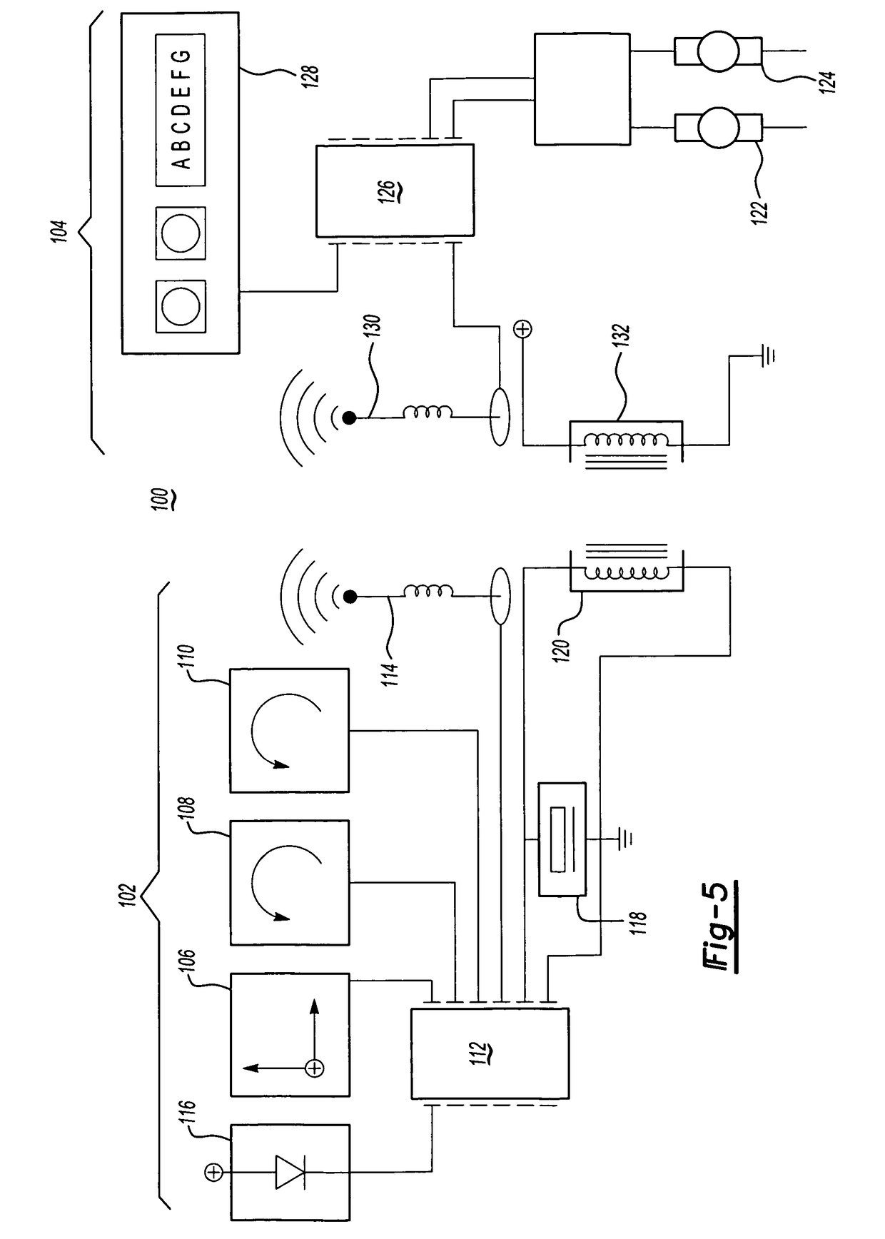
The present invention includes artificial horizon devices for use in a vehicle, whether it is an operator controlled vehicle or an autonomous vehicle. The devices may be a component of a larger system incorporated into a vehicle or a stand-alone device. The device may be provided as part the original equipment of a vehicle or as an aftermarket, add-on device. The device may be portable, temporarily or permanently installed on the vehicle.

The operation of the horizon device may be manually or automatically controlled. For example, the horizon device may be turned on and calibrated as part of the vehicle start up procedures. Alternately, the horizon device may turn on upon the occurrence of particular visibility conditions (e.g. darkness, fog, or the like), weather conditions (e.g. wind, precipitation, or the like), motion of the vehicle (e.g. particular combinations of pitch, roll, and yaw rates), vehicle position (e.g. latitude, longitude, and altitude), combinations thereof, or the...


PUM


Abstract

The present invention includes an artificial horizon device including a sensor unit with a movable platform, at least one actuator linked to the platform, and one or more sensors located on the platform for sensing the position orientation of the platform relative to an external mass or the motion of the platform. The horizon device also includes a processing unit signally connected to the sensors and the at least one actuator. The processing unit is adapted to receive signals from the sensors and send signals to the actuators to move the platform to a horizontal orientation. The horizon device also includes either a display unit comprising an indicator of a horizon line which substantially corresponds to the horizontal orientation of the platform or a secondary device.

Description

FIELD OF THE INVENTIONThe present invention relates to an artificial horizon device and more particularly to an artificial horizon device with improved peripheral visibility.BACKGROUND OF THE INVENTIONArtificial horizon devices have been used extensively in private, commercial and military applications to assist in the manual navigation of vehicles. However, these devices have drawbacks. Typically, these devices have been placed on the control panel in a discrete location within the central field of vision for the operator. Given the space constraints on the control panel, horizon devices have been limited in size; often no more than a few inches across. The limited size makes them difficult to see and requires that the pilot focus directly on the horizon device to obtain visual information.Further, known horizon devices have typically been units that float in a liquid such that as the plane shifts, gravity pulls the unit to the horizontal (e.g. a gimbal) or utilized mechanical gyro...

Claims


Application Information

Patent Timeline
Patent Type & Authority Patents(United States)
IPC IPC(8): G01C23/00G01C15/14G01C19/32G01C19/44
CPCG01C23/005G01C15/14
Inventor CHEOK, KA C.SMID, G. EDZKO
Owner MUNRO & ASSOCS
Why Eureka
Try Eureka