
Pivot mount for firearm sighting devices

a technology of optical sighting device and pivot mount, which is applied in the field of pivot mount for firearm sighting devices, can solve the problems of loss of zero, risk of losing sight mounting or adjusting parts, and inability to remove optical sighting devices from firearms, so as to prevent inadvertent movement or noise

Inactive Publication Date: 2011-03-22
LARUE MARK C
View PDF19 Cites 74 Cited by
  • Summary
  • Abstract
  • Description
  • Claims
  • Application Information

AI Technical Summary

Benefits of technology

[0008]It is a principal feature of the present invention to provide a novel pivot mount mechanism for optical sighting devices and other sight related implements that permits the user of a firearm to manually release the pivot mount from its operative position and rotate the pivot mount to an inoperative sight position without any requirement for the use of tools or other equipment.
[0009]It is another feature of the present invention to provide a novel pivotal firearm sight mount mechanism that stabilizes a sight mount and its sighting device at both the operative and inoperative positions of the sighting device to prevent any inadvertent movement or noise of the sighting device as the firearm is handled.
[0010]It is also a feature of the present invention to provide a novel pivotal firearm sight mount mechanism that is incorporated with a lever actuated sight rail clamping mechanism, thus permitting the entire pivot mount mechanism to be removed from a firearm and replaced without losing the previously sighted zero of the sighting mechanism.
[0011]It is an even further feature of the present invention to provide a novel pivotal firearm sight mount mechanism that is selectively moveable between operative and inoperative positions relative to a firearm without any requirement for the use of tools or special equipment to permit such movement.
[0012]Briefly, the various objects and features of the present invention are realized by providing a pivot mount base that is assembled to or removed from the sight mounting rail of a firearm by a lever actuated cam energized rail clamping mechanism. The pivot mount base is provided with spaced upstanding bosses that provide for rotational and linear movement of a pivot shaft that is located within shaft passages of the bosses. A pivot shaft locator pin extending transversely through the pivot shaft is adapted to be received in selective position controlling relation by pairs of aligned shaft location receptacles defined by one of the bosses or by other structure of the mount base. A sight support device is fixed to and rotates along with the pivot shaft and serves to retain a firearm sighting device, such as a telescope, for example. The sight support device and sighting device are pivotally moveable about the center-line of the pivot shaft between an operative position where the sighting device can be used to sight the firearm on a target and an inoperative position where the sighting device is positioned laterally offset from its operative position. The sight support device, in addition to being mounted in fixed relation with the pivot shaft, is spring energized along with the pivot shaft to secure the sighting device in forcible contact with position controlling surfaces of the mount and thus secure the sighting device against inadvertent movement and noise at both its operative and inoperative positions.

Problems solved by technology

Typically, removal of an optical sighting device from a firearm requires the use of certain tools and equipment and the risk of losing sight mounting or adjusting parts if such an activity is carried out in a field environment.
Moreover, removal of a sighting device from a firearm inevitably results in the loss of zero, thus requiring the firearm to be again sighted in after the sighting device has been re-installed on the firearm.
In the tactical environment, military or law enforcement personnel do not ordinarily have sufficient available time for sight removal or installation, so the need for changes of sighting devices has largely remained unsatisfied.

Method used


Image

  • Pivot mount for firearm sighting devices
  • Pivot mount for firearm sighting devices
  • Pivot mount for firearm sighting devices

Examples


Embodiment Construction

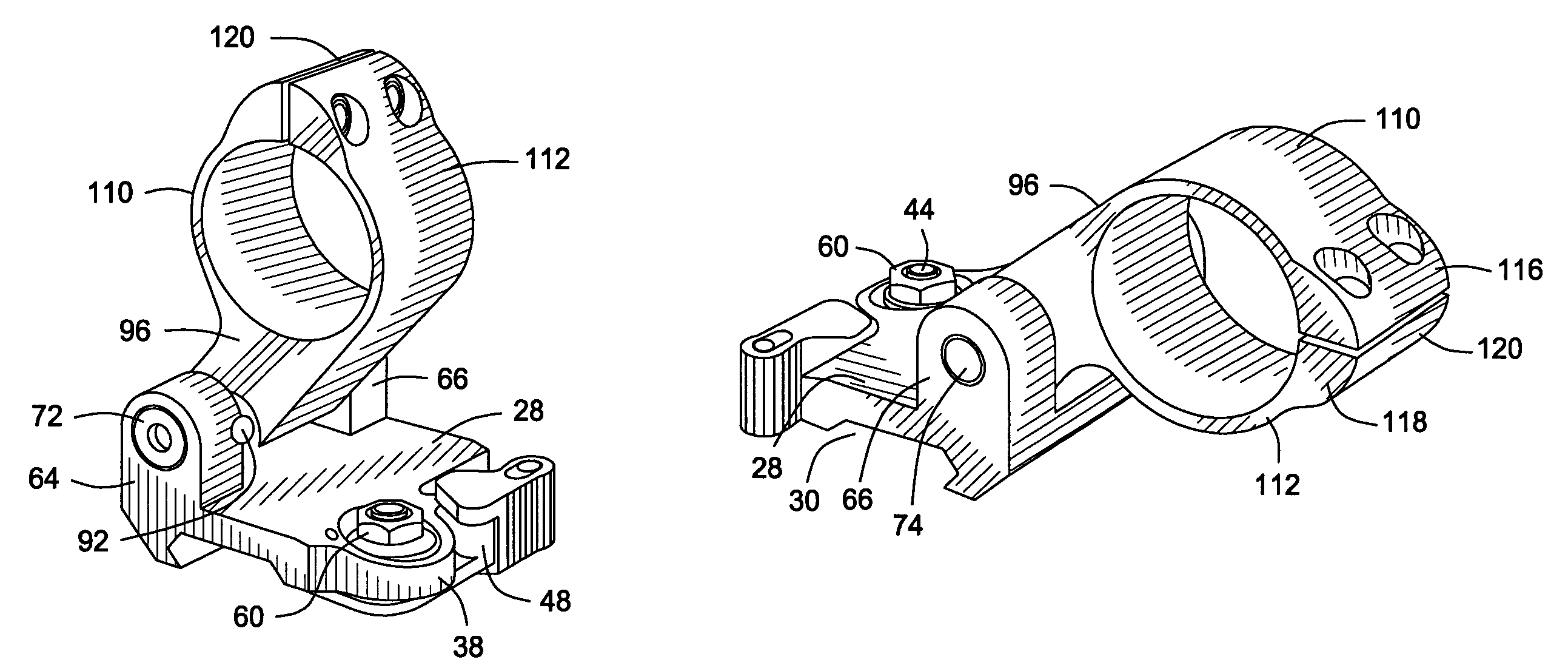
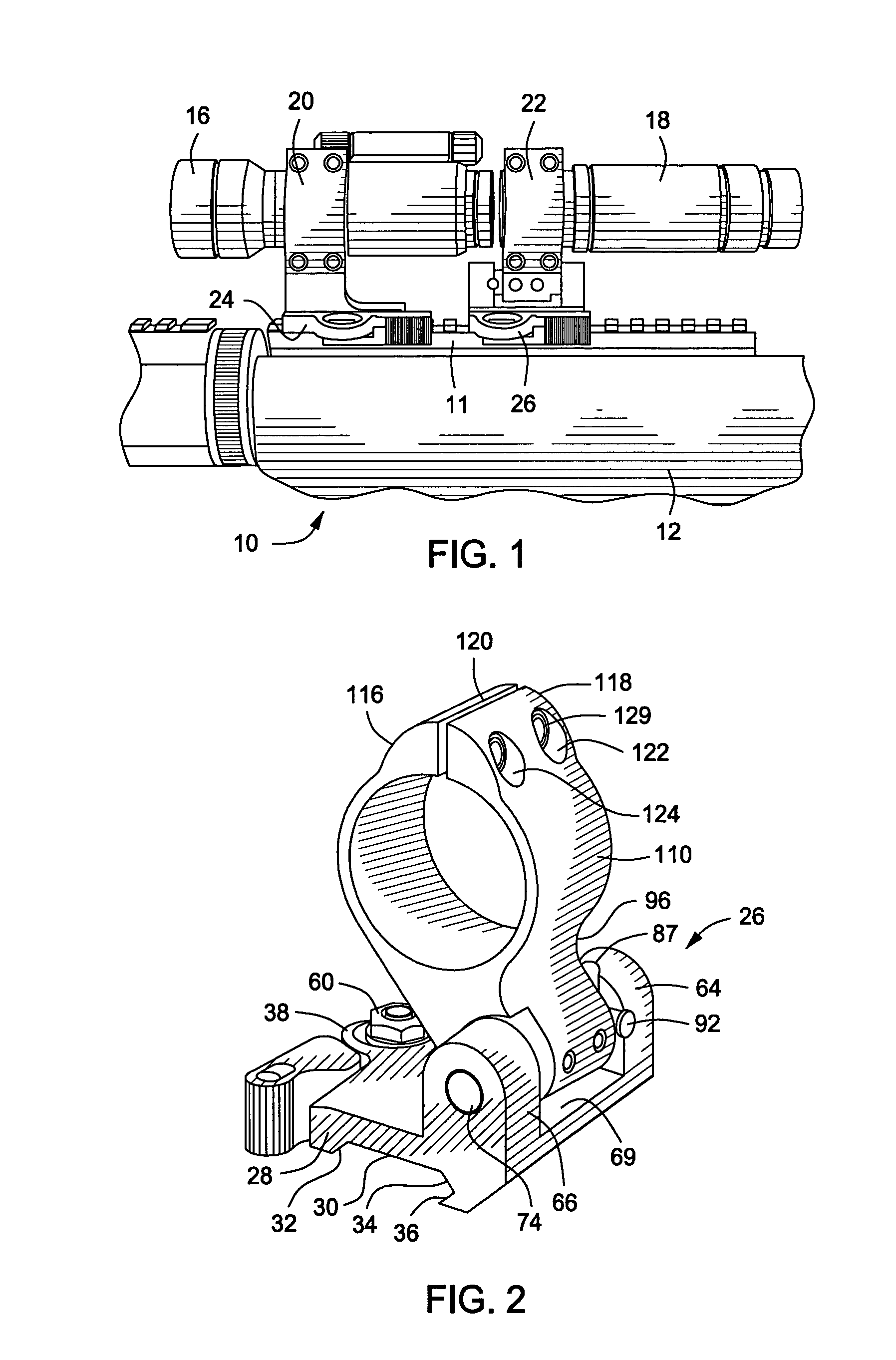
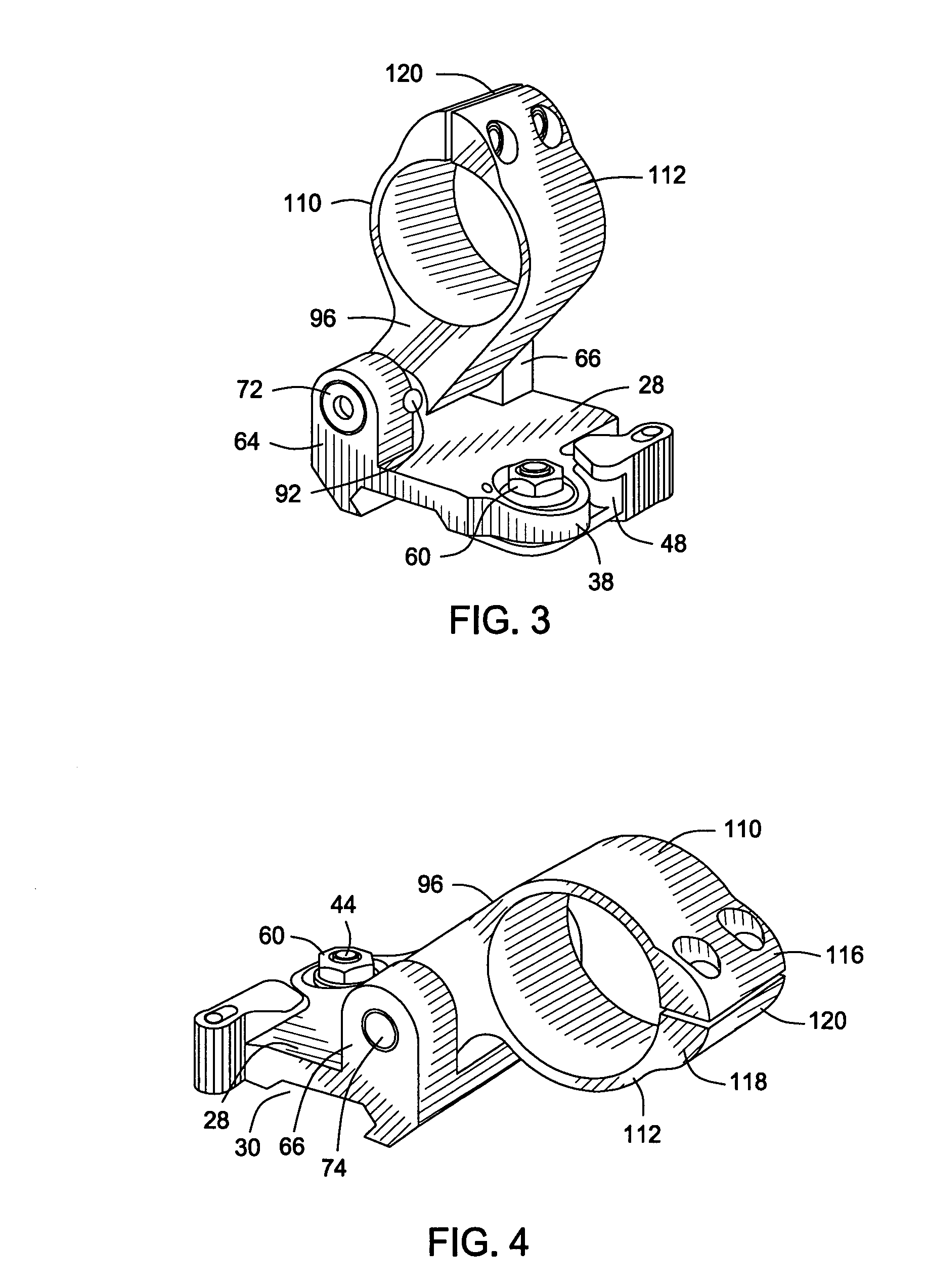
[0026]Referring now to the drawings and first to the elevational view of FIG. 1, there is shown a portion of a tactical firearm generally at 10 having a Picatinny or other sight mounting rail 11 fixed to or integral with the receiver 12 of the firearm. The sight mounting rail 11 defines upwardly facing angulated clamping support surfaces and downwardly facing angulated clamping surfaces as will be explained in detail below. A pair of sighting devices 16 and 18 are positioned in tandem or series on the firearm, being supported and positioned by sight support members 20 and 22 that are in turn supported and positioned on the firearm by lever actuated sight mount rail clamp mechanisms 24 and 26. The lever actuated sight mount rail clamp mechanism shown generally at 26 in FIG. 2 has a mounting base structure 28 that is constructed essentially according to the teachings of U.S. Pat. No. 7,272,904 of LaRue, which patent is incorporated herein by reference for all purposes. A base location...


PUM


Abstract

A pivot mount base is assembled to or removed from the sight mounting rail of a firearm by a lever actuated cam energized rail clamping mechanism. The pivot mount base supports and provides for rotational and linear movement of a pivot shaft. A pivot shaft locator pin extending transversely through the pivot shaft is adapted to be selectively received in position controlling relation by pairs of aligned shaft location receptacles defined by the pivot mount base. A sight support device is fixed to the pivot shaft and serves to retain a firearm sighting device. The sight support device and sighting device are moveable between an operative position where the sighting device can be used to sight the firearm on a target and an inoperative position where the sighting device is positioned laterally offset from its operative position. The sight support device is pivotally mounted by the pivot shaft and is spring energized to secure the sighting device against inadvertent movement and noise at its operative and inoperative positions.

Description

BACKGROUND OF THE INVENTION[0001]1. Field of the Invention[0002]The present invention relates generally to firearms and more particularly to firearm sighting devices. Even more specifically the present invention concerns a pivot mount by which a particular firearm sighting device, such as an optical or laser sighting device is releasably mounted to the sight mounting rail of a tactical firearm by a locking lever operated clamp mechanism and, when so mounted, a sight support portion of the mount is pivotally moveable between an operative position at which the sighting device is useable for the purpose of sighting on a target and an inoperative position at which the sighting device is positioned out of the normal line of sight of the firearm. The present invention also concerns a pivot mount for a firearm sighting device or other firearm related implement that is adapted for manual unlocking and pivotal movement, without necessitating the use of any tools or other equipment.[0003]2. D...

Claims


Application Information

Patent Timeline
IPC IPC(8): F41G1/387
CPCF41G11/003F41G11/008
Inventor LARUE, MARK C.
Owner LARUE MARK C
Features
  • Generate Ideas
  • Intellectual Property
  • Life Sciences
  • Materials
  • Tech Scout
  • Unparalleled Data Quality
  • Higher Quality Content
  • 60% Fewer Hallucinations
Learn More