Optical connector plug

US20120057831A1Active Publication Date: 2012-03-08SEIKOH GIKEN
4 Cites 9 Cited by

Patent Information

Authority / Receiving Office
US · United States
Current Assignee / Owner
Publication Date
2012-03-08

Smart Images

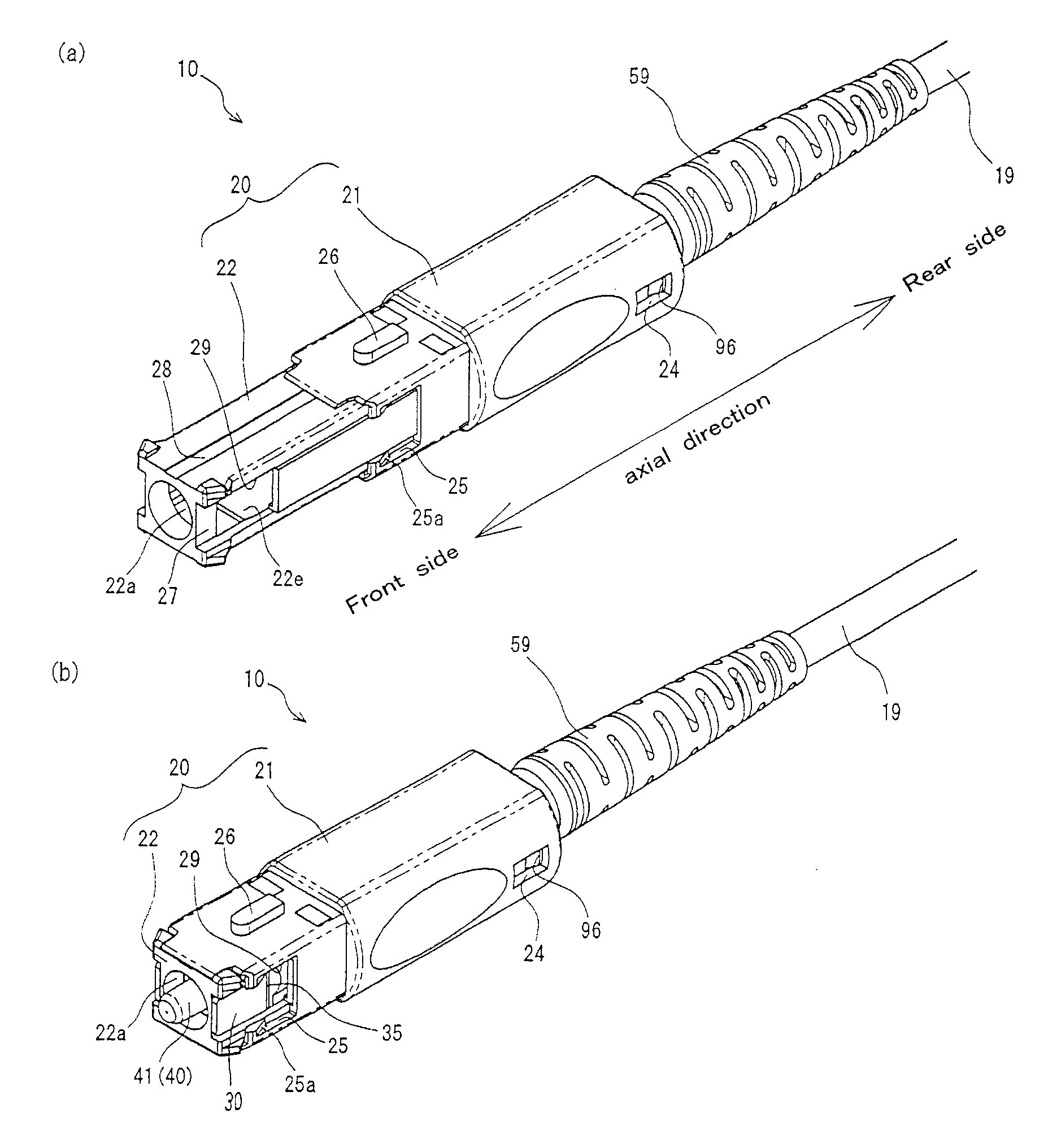
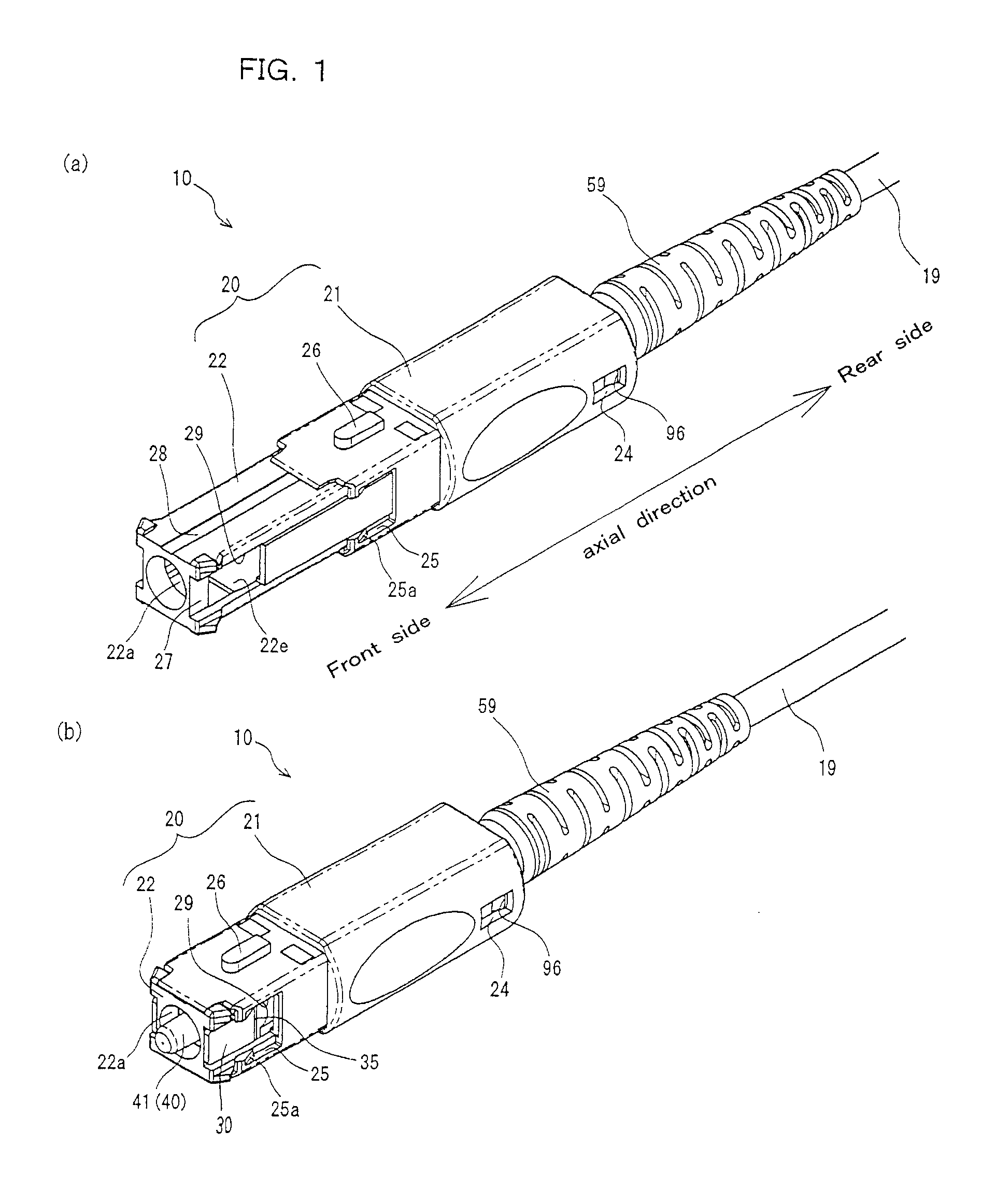
  • Figure 1
    Figure 1
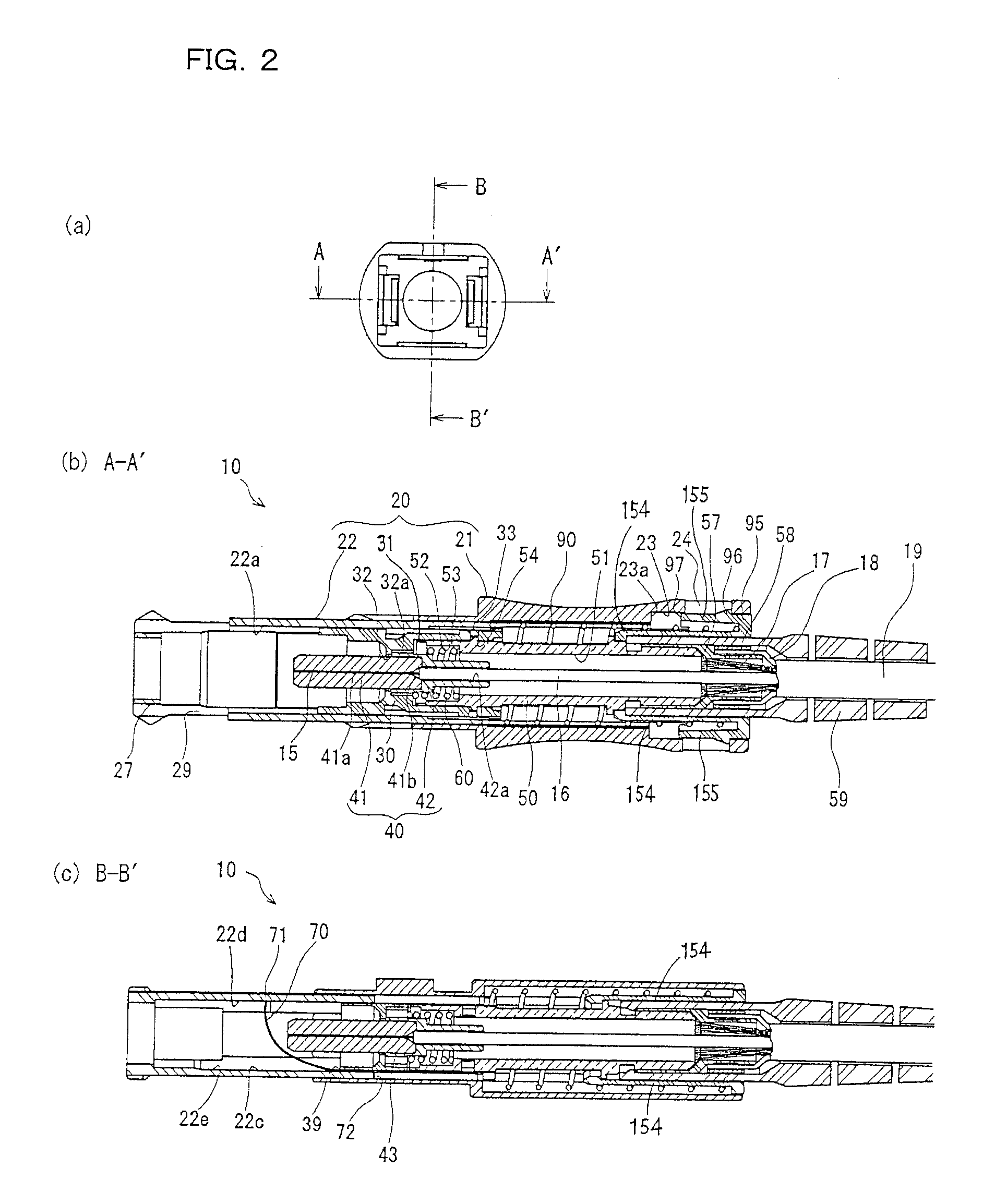
  • Figure 2
    Figure 2
  • Figure 3
    Figure 3
Patent Text Reader

Abstract

An optical connector plug incorporates a coil spring to bias a shutter holding member to the front side of an axial direction with respect to a plug frame and minimizes the entire length. The plug has a housing that includes a grip member and a shutter holding member that move relatively in the axial direction and the plug frame has an extension state in which the grip member moves to the rear side of the axial direction of the shutter holding member and a reduction state in which the grip member moves to the front side of the axial direction of the shutter holding member. A biasing member that biases the shutter holding member to the front side of the axial direction with respect to the plug frame and a biasing member receiving member that is connected to the plug frame are provided.
Need to check novelty before this filing date? Find Prior Art

Description

BACKGROUND OF THE INVENTION

[0001] 1. Field of the Invention

[0002] The present invention relates to an optical connector plug that holds front ends of optical fibers and couples the optical fibers to each other.

[0003] 2. Description of the Related Art

[0004] In the related art, optical coupling between optical fibers used for optical communication is performed using an optical connector. The optical connector includes optical connector plugs that hold front ends of optical fibers and an optical connector adapter that fix the optical connector plugs to each other and performs optical coupling of the optical fibers.

[0005] As the optical connector, an SC-type optical connector (complying with IEC 61754-4) that couples the optical fibers to each other using a ferrule barrel-shaped body (with the outer diameter of 2.5 mm) for holding the optical fibers or a miniaturized MU-type optical connector (complying with IEC 61754-6) using a ferrule barrel-shaped body (with the outer diameter of 1.25 mm)...

Examples

first embodiment

[0034]FIGS. 1A and 1B are perspective views of an optical connector plug 10 according to an embodiment of the present invention and FIGS. 2A to 3C are front views, cross-sectional views taken along the line A-A′, and cross-sectional views taken along the line B-B′ of the optical connector plug 10. FIG. 4 is an exploded perspective view of the optical connector plug 10.

[0035]As illustrated in FIGS. 1A to 4, the optical connector plug 10 according to this embodiment has a shape in which the optical connector plug 10 can be coupled to an SC-type optical connector adaptor to be described below. The optical connector plug 10 includes a housing 20, a plug frame 30 that is held movably in an axial direction (toward the front side and the rear side of an axial direction) in the housing 20, a ferrule 40 that holds an optical fiber 15 for optical coupling and is inserted from the rear of the plug frame 30, a stop ring 50 that has a front end engaged with a rear end of the plug frame 30, and a...