Wheel loader

Active Publication Date: 2012-10-02
KUBOTA LTD
View PDF14 Cites 10 Cited by
  • Summary
  • Abstract
  • Description
  • Claims
  • Application Information

AI Technical Summary

Benefits of technology

[0028]As the brake is provided for braking the power inputted to the differential device, the brake can be applied while the torque is small. Hence, the lo

Problems solved by technology

In the course of this, when the scooping action of the bucket is started with the operator moving his/her foot off the traveling pedal to the brake pedal, during the period from the detachment of the foot from the traveling pedal to stepping on the brake pedal with the same foot, there occurs a problem that the machine body may be inadvertently moved rearward due to the reaction force from the earth/sand or the like.
In this case; however, there will occur momentary suspension in the series of operations from the forward traveling to the scooping action, during the drive's moving

Method used


Image

  • Wheel loader
  • Wheel loader
  • Wheel loader

Examples


Embodiment Construction

[0044]Next, embodiments of the present invention will be described with reference to the accompanying drawings.

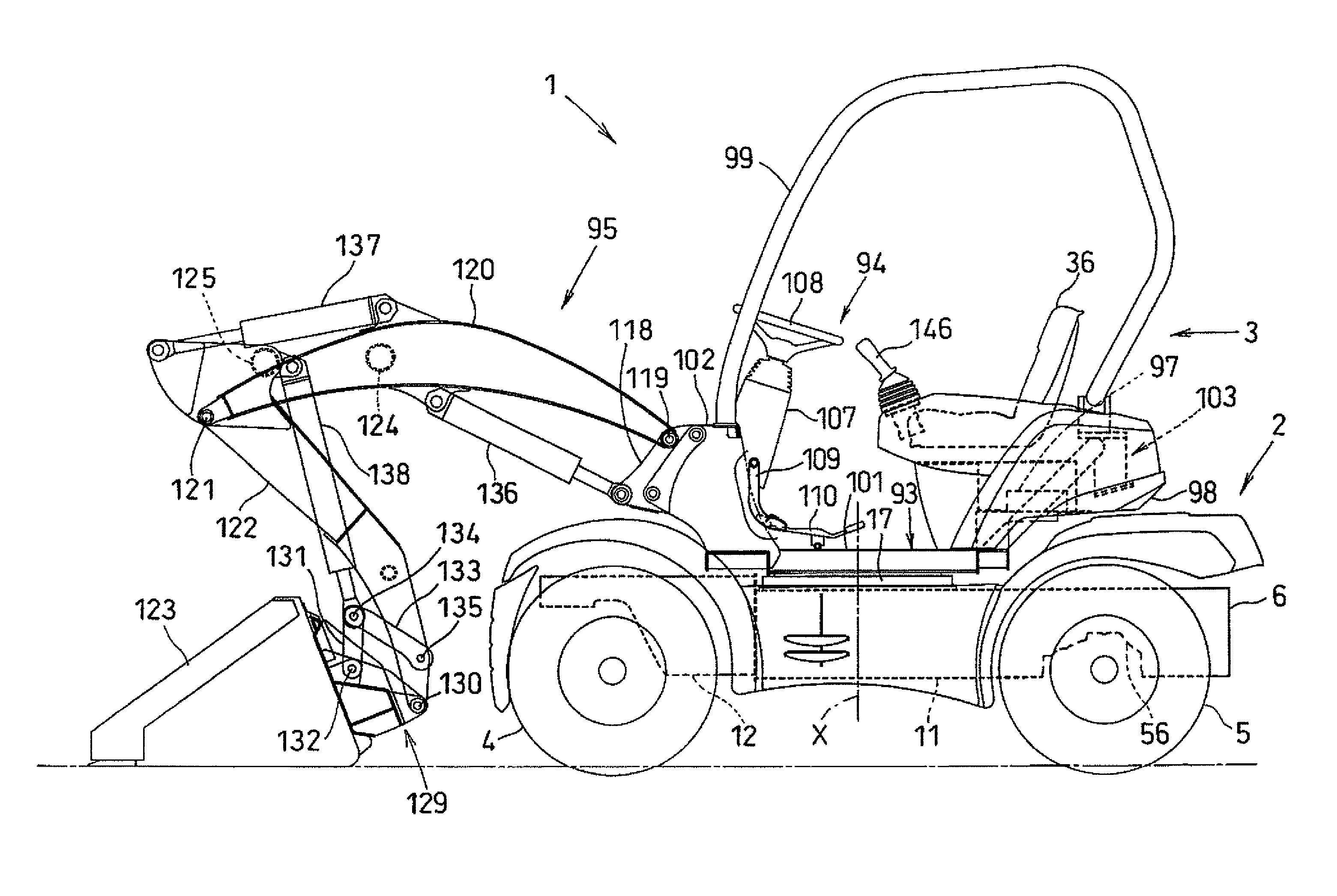
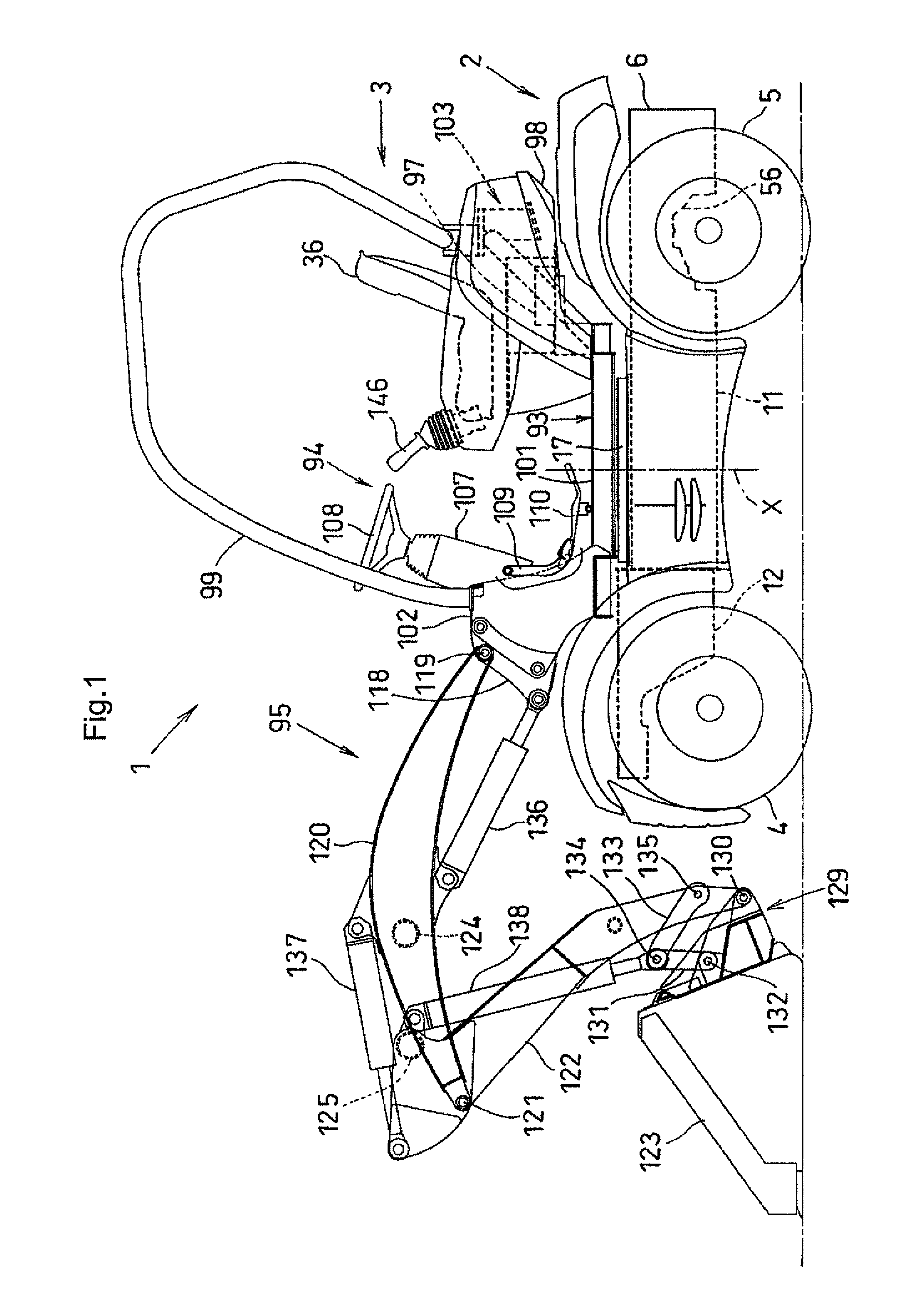
[0045]In FIGS. 1 through 3, numeral 1 denotes a compact wheel loader for city use, to be used in home gardening for example. This wheel loader 1 includes a traveling body 2 disposed on the lower side and a swivel body 3 disposed on the upper side.

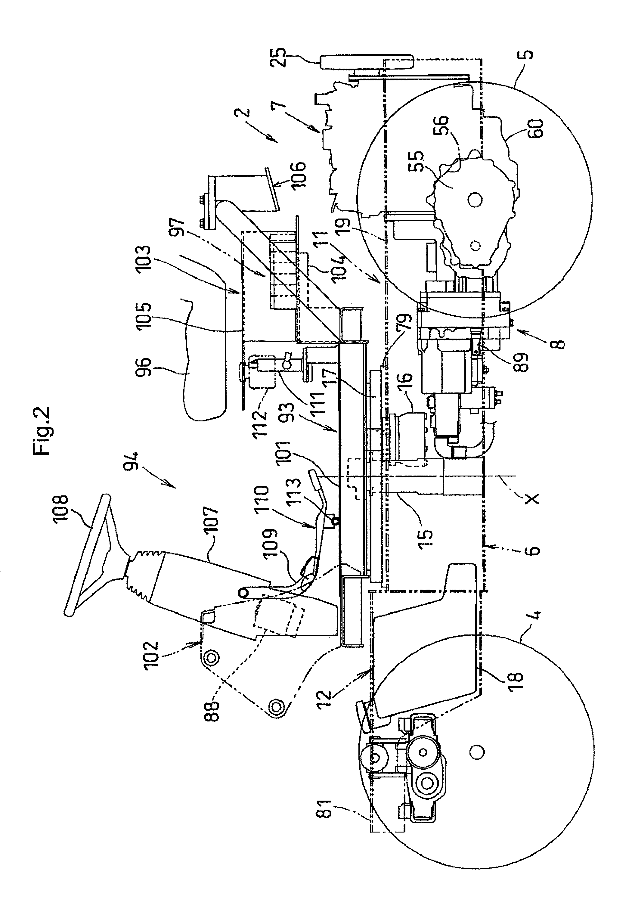
[0046]The traveling body 2 comprises a wheel type traveling body 2 travelable by a pair of right and left front wheels 4 and a pair of right and left rear wheels 5, a traveling machine body 6 supported by the front and rear wheels 4, 5, an engine 7 mounted on the traveling machine body 6, a traveling line main transmission mechanism 8 for transmitting power of the engine 7 to the rear wheels 5, and a front wheel power transmission mechanism 9 for transmitting power taken off the traveling line main power transmission mechanism 8 to the front wheels 4.

[0047]The traveling machine body 6 includes a main frame 11 and a front frame 12 p...


PUM


Abstract

A wheel loader having good operability. The wheel loader has a machine body travelably supported on wheels; a working device supported on the machine body, the working device having a boom swingably supported at its base end side on the machine body, an arm swingably supported at and connected to the forward end side of the boom, and a working tool swingably provided on the forward end side of the arm; travel operation means for performing travel operation of the machine body; and a brake for braking, when the travel operation means is not operated and the arm is swung, the wheels in operative association with the swing of the arm.

Description

BACKGROUND OF THE INVENTION[0001]1. Technical Field[0002]The present invention relates to wheel loader having a machine body travelably supported on wheels and a work device mounted on the machine body.[0003]2. Background Art[0004]Conventionally, there is provided a wheel loader having a machine body travelably supported on front and rear wheels, and a work device supported to a front portion of the machine body, the work device including a boom having a base portion thereof supported to the machine body to be vertically pivotable, an arm pivotally connected to the leading end of the boom to be pivotable in the fore / aft direction, and a work implement pivotally attached to the leading end of the arm (see Patent Document 1).Patent Document 1: Japanese Patent Application “Kokai” No. 2005-171608[0005]In the case of the conventional wheel loaders, e.g. one having a bucket, as the work implement, oriented to the front side, with the rear face side thereof being pivoted to the leading end...

Claims


Application Information

Patent Timeline
IPC IPC(8): B60K17/00
CPCB60T1/062E02F9/02E02F9/2037E02F9/22F16D65/186F16D2121/02F16D2121/12B60T7/00B60T7/12
Inventor SUMIYOSHI, RYOHEISUZUKI, KUNIHIRO
Owner KUBOTA LTD
Why Eureka
Try Eureka