Structural lintel assembly and building construction method using the same

a technology of structural lintel and construction method, which is applied in the direction of structural elements, building components, shaping building parts, etc., can solve the problems of interference to the welding of spacing tubes, time-consuming, costly and potentially hazardous process, and the outer surface of concrete in contact with the form often does not present a perfectly aligned and smooth surface, so as to achieve less time-consuming, less dangerous, and more economical

Active Publication Date: 2011-03-22
VIEIRA JOSE
View PDF60 Cites 22 Cited by
  • Summary
  • Abstract
  • Description
  • Claims
  • Application Information

AI Technical Summary

Benefits of technology

[0016]By prefabricated, it is meant an assembly manufactured in advance in factory, especially in standard sections that can be easily shipped and used directly on the site of construction. The assembly can be used for example in the construction of a building or section of a building, more specifically for making a concrete floor able to structurally support a masonry wall.
[0025]It has to be understood that the number and size of each prefabricated form assembly provided in step a) of the above method, depends on the size and shape of the final mould to assemble, and thus to the final concrete floor to build. As aforesaid, each assembly is manufactured in advance, especially in standard sections that can be easily shipped and assembled on the site of construction to form the desired moulds.
[0030]Advantages of the present invention include that the proposed method and device allows for the securing or anchoring of structural lintels to concrete slabs or beams through a set of relatively quick, ergonomic and unhazardous steps, thanks mainly to the fact that no more welding process is required in place the lintel arrives on the site of construction already secured to the form plate.
[0032]The proposed method and device is thus more economical, less time-consuming and less dangerous than the conventional methods and devices detailed above used for anchoring structural lintels to concrete slabs or beams.
[0035]A further advantage of using the prefabricated form assembly and method of the present invention resides in the fact that there is no more need for performing steps in order to ensure that the outer surface of conventional form plates be in register or proper alignment with a corresponding adjacent outer surface of the concrete slab or beam into which the form plates and their corresponding anchoring elements are embedded. Accordingly, and as mentioned above the anchoring of the prefabricated form assembly may be performed by a single class of building trades, namely concrete / form workers and / or masonry workers without requiring steel workers for performing tedious, time-consuming and potentially dangerous torching and welding for the correction of imperfections.

Problems solved by technology

Regardless of whether the spacing tubes and bearing plates are welded sequentially or as a pre-assembled unit to the bearing plate, the welding of the spacing tubes to the bearing plates is typically considered to be a tedious, time-consuming, costly and potentially hazardous process.
Indeed, when the moulding forms are removed from the cured or hardened concrete, the outer surface of the concrete in contact with the forms often does not present a perfectly aligned and smooth surface.
Sometimes, the imperfections in the outer surface of the concrete slab or beam are such that such imperfections in themselves cause interference to the welding of the spacing tubes to the outer surface of the bearing plate.
Such on-site modifications require that specialized and skilled workmen spend a considerable amount of time.
The delays caused by the need for a correction of imperfections in the alignment of the outer surface of the bearing plates relative to the outer surface of the concrete slab or beam sometimes slow down other steps in the overall construction of a building.
Also, the required on-site modifications are sometimes of the type that may be potentially hazardous such as in situations wherein a torch is required for cutting through a portion of a bearing plate or the like.

Method used


Image

  • Structural lintel assembly and building construction method using the same
  • Structural lintel assembly and building construction method using the same
  • Structural lintel assembly and building construction method using the same

Examples


Embodiment Construction

[0048]In the following description, similar features in the drawings have been given similar reference numerals and in order to lighten the figures, some elements are not referred to in some figures if they were already identified in a preceding figure.

[0049]Also, in order to ease the reading of following description, it will always be considered that the concrete floor described is built upon a pre-existing inferior level of a building. In other word, the concrete floor described corresponds to at least the second level of a building. However it has to be understood that the object and method of the invention may be used for the construction of each floor of the building in construction.

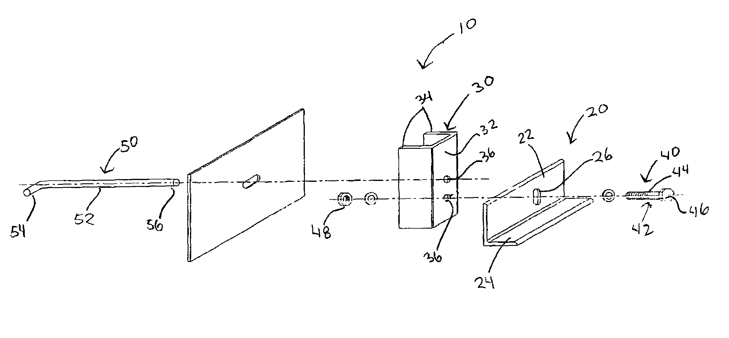
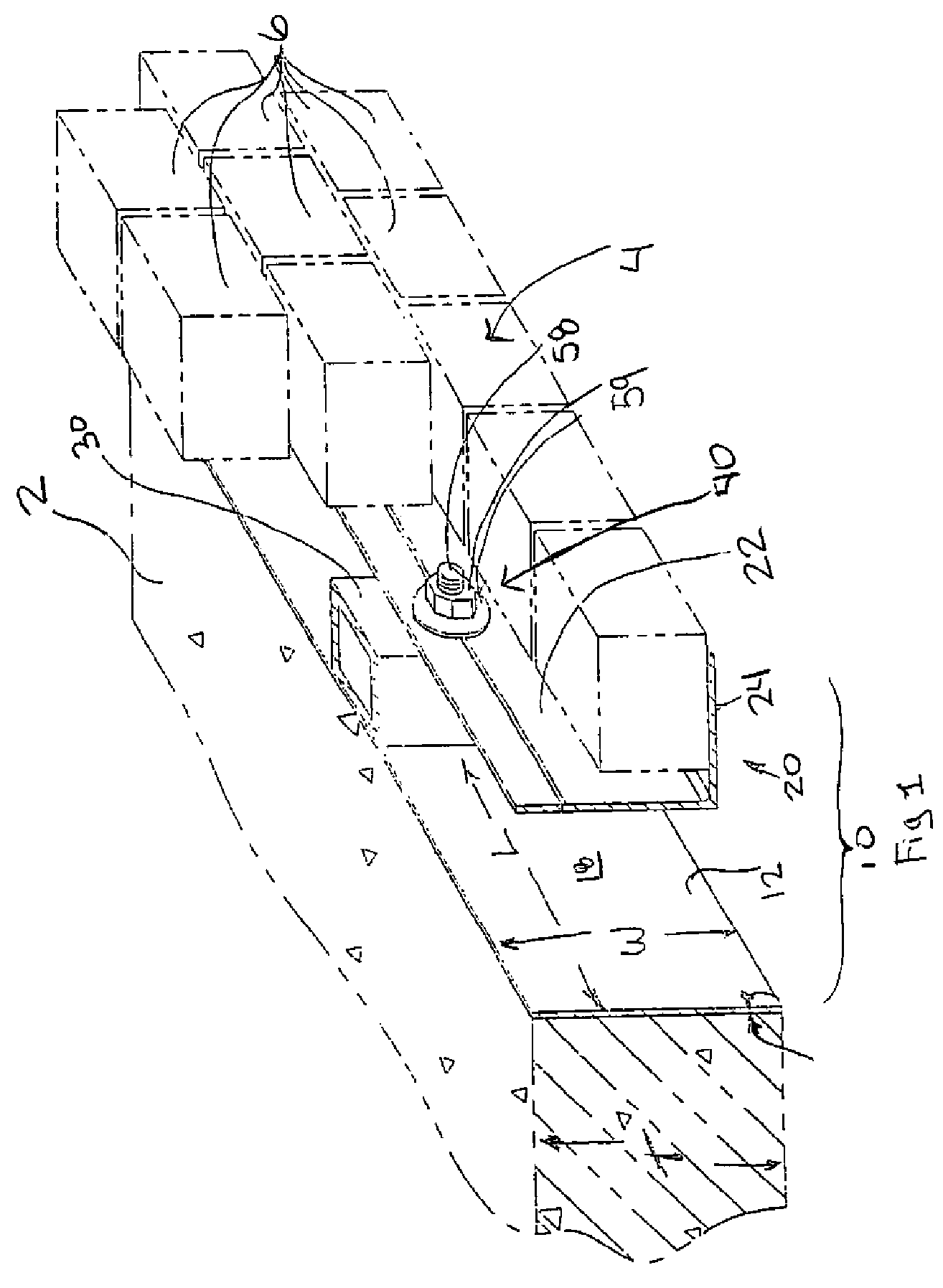
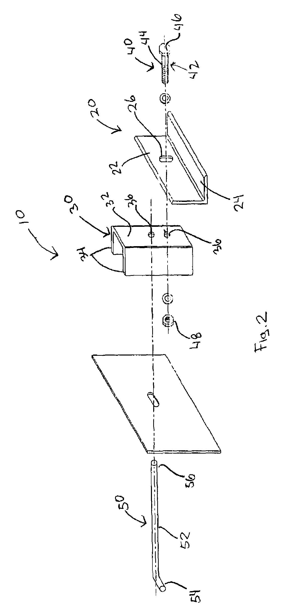
[0050]As aforesaid, and referring to FIG. 1, the present invention concerns a prefabricated form assembly 10 adapted to both built a concrete floor 2 and a masonry wall 4 structurally retained by the concrete floor 2. The assembly 10 is manufactured in advance, especially in standard sections that c...


PUM


Abstract

A prefabricated form assembly for making a concrete floor is disclosed. The form comprises an elongated form plate having a front for forming and retaining a flowable concrete material before it sets, anchor elements extending from the back face of the form plate, and being destined to be embedded into the concrete floor; and an L-shaped lintel having a back wall connected to the front face of the form plate and a bearing wall for supporting a masonry wall. Advantageously the construction of a concrete floor adapted to structurally retain a masonry wall using prefabricated form assemblies according to the invention no more requires the use of different groups of workers from different building trades as in the prior art, only one group of workers is required.

Description

FIELD OF THE INVENTION[0001]The present invention pertains to the general field of building construction, building components and methods of construction and is particularly directed to an adjustable structural lintel assembly used for making and connecting a concrete floor with external walls, and a construction method using the same.BACKGROUND OF THE INVENTION[0002]Brick, stone and concrete structures are used extensively in the construction or building of residential, industrial, commercial, agricultural and other applications. Indeed, many structures are built from wood, brick, stone, concrete or a combination of these materials or similar materials because of their many advantages including strength, durability, temperature and sound insulation, fire resistance, general attractiveness and ease of maintenance.[0003]Gravity forces acting on the facing material of a given structure can be transferred to major structural elements of the building, for example, beams, columns, concre...

Claims


Application Information

Patent Timeline
Patent Type & Authority Patents(United States)
IPC IPC(8): E04H1/00
CPCE04C3/02E04C2003/023
Inventor VIEIRA, JOSE
Owner VIEIRA JOSE
Why Eureka
Try Eureka