
Accelerator pedal

a technology of accelerator pedals and accelerators, applied in the direction of mechanical control devices, instruments, process and machine control, etc., can solve the problems of poor fuel efficiency, poor throttle valve operation accuracy, increased driver fatigue, etc., to improve the operation feeling, reduce driver fatigue, and accurate throttle valve operation

Inactive Publication Date: 2011-03-22
DONG HEE IND
View PDF12 Cites 10 Cited by
  • Summary
  • Abstract
  • Description
  • Claims
  • Application Information

AI Technical Summary

Benefits of technology

The present invention is a mechanical organ type accelerator pedal that improves the operation feeling and reduces driver's fatigue. It includes an organ type pedal that controls the opening / closing operation of a throttle valve in a carburetor through an acceleration cable. The invention includes a housing, a foot plate, a pedal arm, a carrier, and a cover. The foot plate is hingedly connected to the housing and can rotate in the vertical direction of the housing by driver's stepping force on the pedal. The pedal arm is connected to the acceleration cable and can rotate inside the housing. The carrier penetrates the housing and connects the foot plate and the pedal arm with an elastic means to apply restoring force. The cover is coupled with the housing to cover an opening at one side of the housing and has a center protrusion that serves as a rotating fulcrum. The technical effects of the invention are improved operation feeling, reduced driver's fatigue, accurate operation of the throttle valve, and upgraded interior look of the vehicle.

Problems solved by technology

However, a conventional mechanical accelerator pedal gives a driver a rough operation feeling, accordingly, a problem is found in that the rough operation feeling increases driver's fatigue.
In addition, since the opening / closing of the throttle valve cannot be operated with accuracy, unexpected waste of fuel is inevitably generated, thus making worse fuel efficiency as well as stability.

Method used


Image

  • Accelerator pedal
  • Accelerator pedal
  • Accelerator pedal

Examples


Embodiment Construction

Hereinafter, embodiments of the invention will be described with reference to the accompanying drawings.

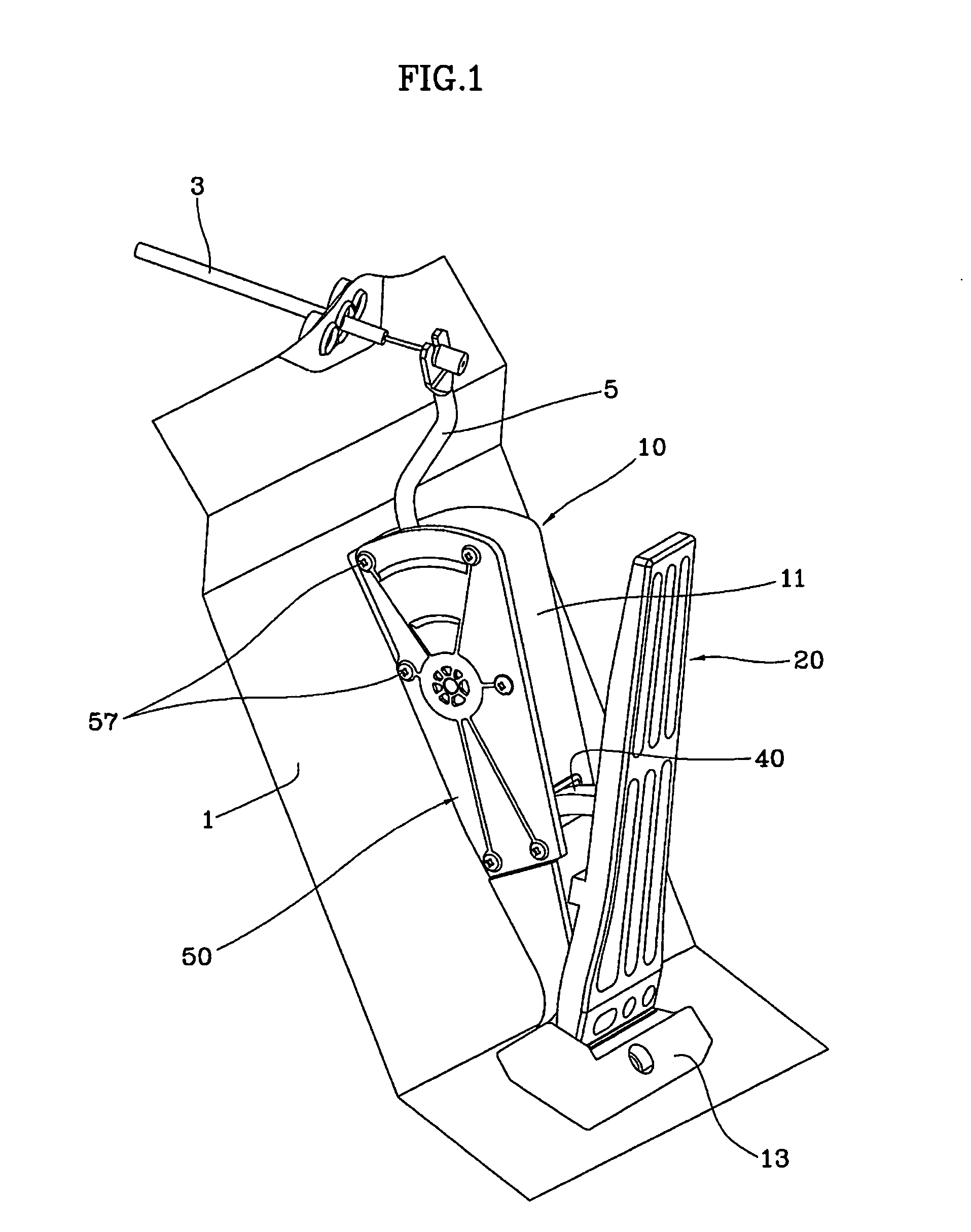
FIG. 1 is a perspective view illustrating a mechanical organ type accelerator pedal according to the present invention.

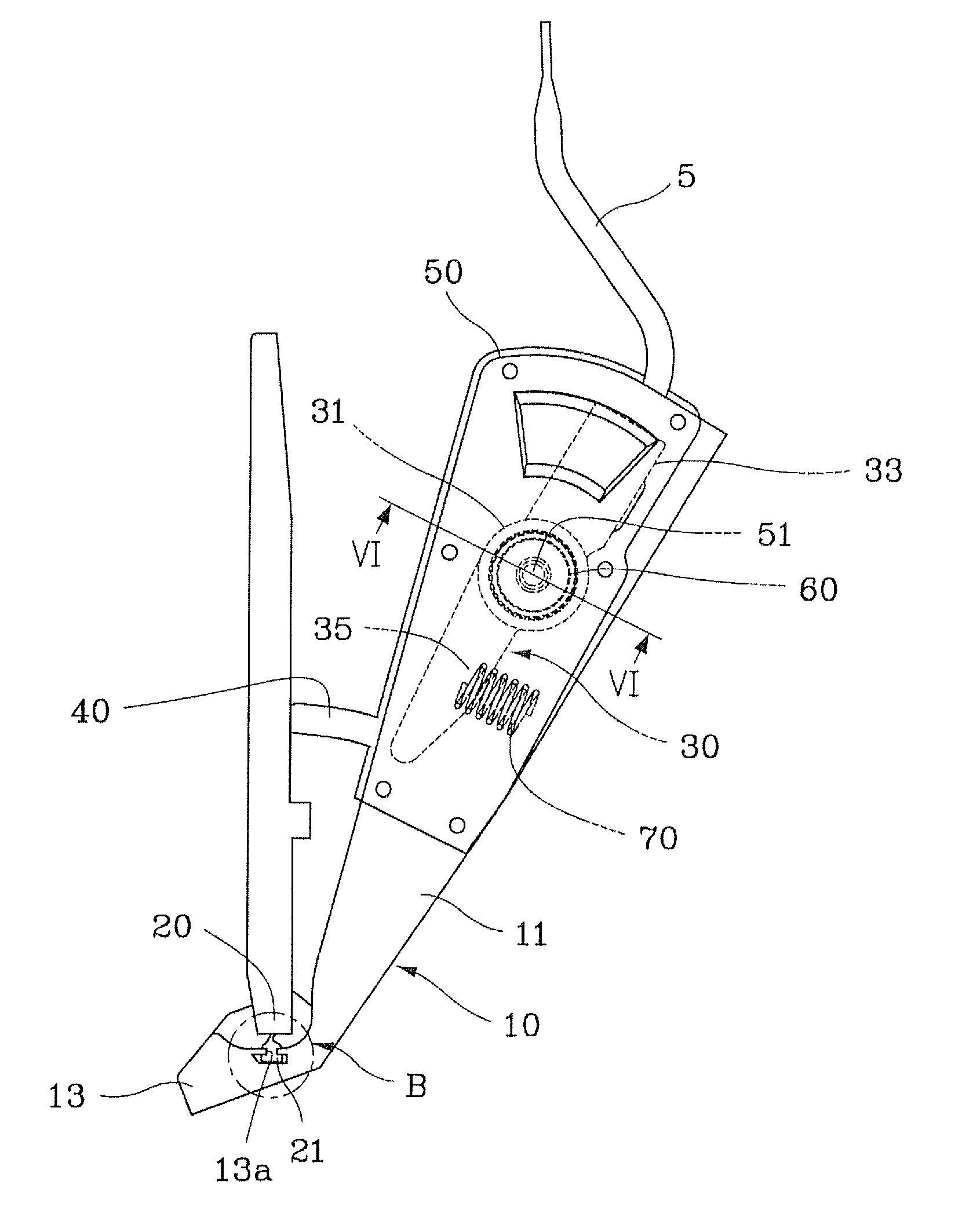
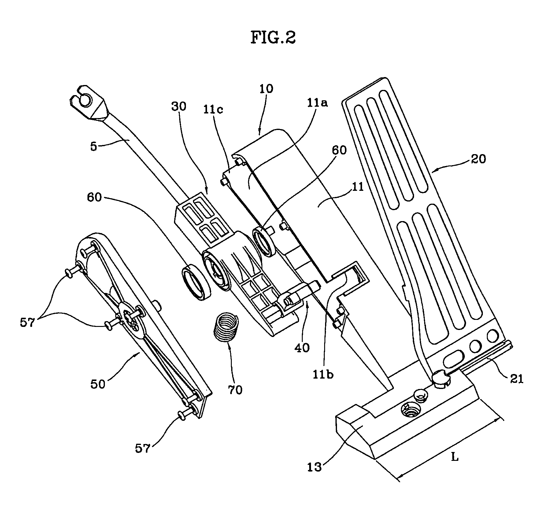
A mechanical organ type accelerator pedal according to the present invention, as shown in FIGS. 1 to 6, is composed of a housing 10 that is fixedly disposed to a floor panel 1 under a driver's seat, a foot plate 20 whose one end is coupled hingedly with the housing 10 and the other end is disposed to be rotated in a vertical direction of the housing 10 by driver's stepping force on the pedal, a pedal arm 30 that is coupled with one end of a connecting cable 5 connected to an acceleration cable 3 and disposed to be rotatable inside the housing 10 in conjunction with the operation of the foot plate 20, a carrier 40 that penetrates the housing 10 to connect the foot plate 20 and the pedal arm 30, an elastic means that is disposed to be supported by the housing 10 and...


PUM


Abstract

An accelerator pedal which has a housing; a foot plate coupled hingedly with the housing; a pedal arm; a carrier that penetrates the housing to connect the foot plate and the pedal arm; a compression spring to apply restoring force to the carrier; and a cover. The accelerator pedal has a plate coupling part that extends from a body of the housing. The foot plate has a first end is inserted into a coupling hole of the plate coupling part and is coupled hingedly with the housing. The compression spring is disposed between a lower side of the body of the housing and the carrier.

Description

BACKGROUND OF THE INVENTION1. Field of the InventionThe present invention relates to a mechanical organ type accelerator pedal, and particularly, to a mechanical organ type accelerator pedal to improve an operation feeling and reduce driver's fatigue while achieving stability and economic feasibility.2. Description of the Related ArtGenerally, an accelerator pedal of a vehicle is a device which regulates an inhalation quantity of fuel-air mixture in a gasoline engine, and regulates an injection quantity of fuel in a diesel engine, to control number of revolution of an engine. The accelerator is classified into a pendant type which is hung on a dashboard and an organ type which is disposed on a floor panel depending on a mounting structure.Recently, a mechanical accelerator pedal is widely used to control the quantity of combustion by opening / closing a throttle valve in a carburetor through an acceleration cable.However, a conventional mechanical accelerator pedal gives a driver a ro...

Claims


Application Information

Patent Timeline
Patent Type & Authority Patents(United States)
IPC IPC(8): G05G1/30G05G1/445
CPCG05G1/30G05G1/483G05G5/03Y10T74/20534Y10T74/20528B60K26/04
Inventor KIM, KYUNG MINLEE, KWANG HYUCKMO, YONG HWAN
Owner DONG HEE IND
Learn More