Converter motor

a converter motor and electric motor technology, applied in the direction of electrical apparatus, dynamo-electric machines, supports/enclosements/casings, etc., can solve the problems of inefficiency at partial loads, fixed speed and rotation direction, and need for separate start-up devices, etc., to achieve less installation space, cost-friendly, and easy electrical connection

Inactive Publication Date: 2011-03-22
ROBERT BOSCH GMBH
View PDF4 Cites 20 Cited by
  • Summary
  • Abstract
  • Description
  • Claims
  • Application Information

AI Technical Summary

Benefits of technology

[0010]The object of the present invention, therefore, is to create a converter motor that requires less installation space than the existing designs. In addition, the inventive converter motor should be more cost-favorable, should enable easier electrical connections, and make it possible to regulate rotational speed using suitable sensors. A converter motor should therefore be provided that is suitable as a modern replacement for the IEC standard motors, with or without converters.

Problems solved by technology

Asynchronous motors of this type have various disadvantages, however, such as a fixed speed and direction of rotation, and the fact that a separate start-up device is required.
In addition, they are inefficient at partial loads, and the cos phi power factor is poor.
In addition, active braking cannot be carried out with motors of this type.
The act of providing a converter has various disadvantages, too, such as additional costs, a greater amount of space required in the switch cabinet, the development of additional heat in the switch cabinet, and noise radiation resulting from the pulse-width modulation (PWM), and the resultant need for interference suppressor filters.
The disadvantage of systems of this type is that the converter unit is often just as large as the motor itself.
A position pick-up for regulating rotational speed or position is basically not integrated, or doing so requires high additional costs.

Method used


Image

  • Converter motor
  • Converter motor
  • Converter motor

Examples


Embodiment Construction

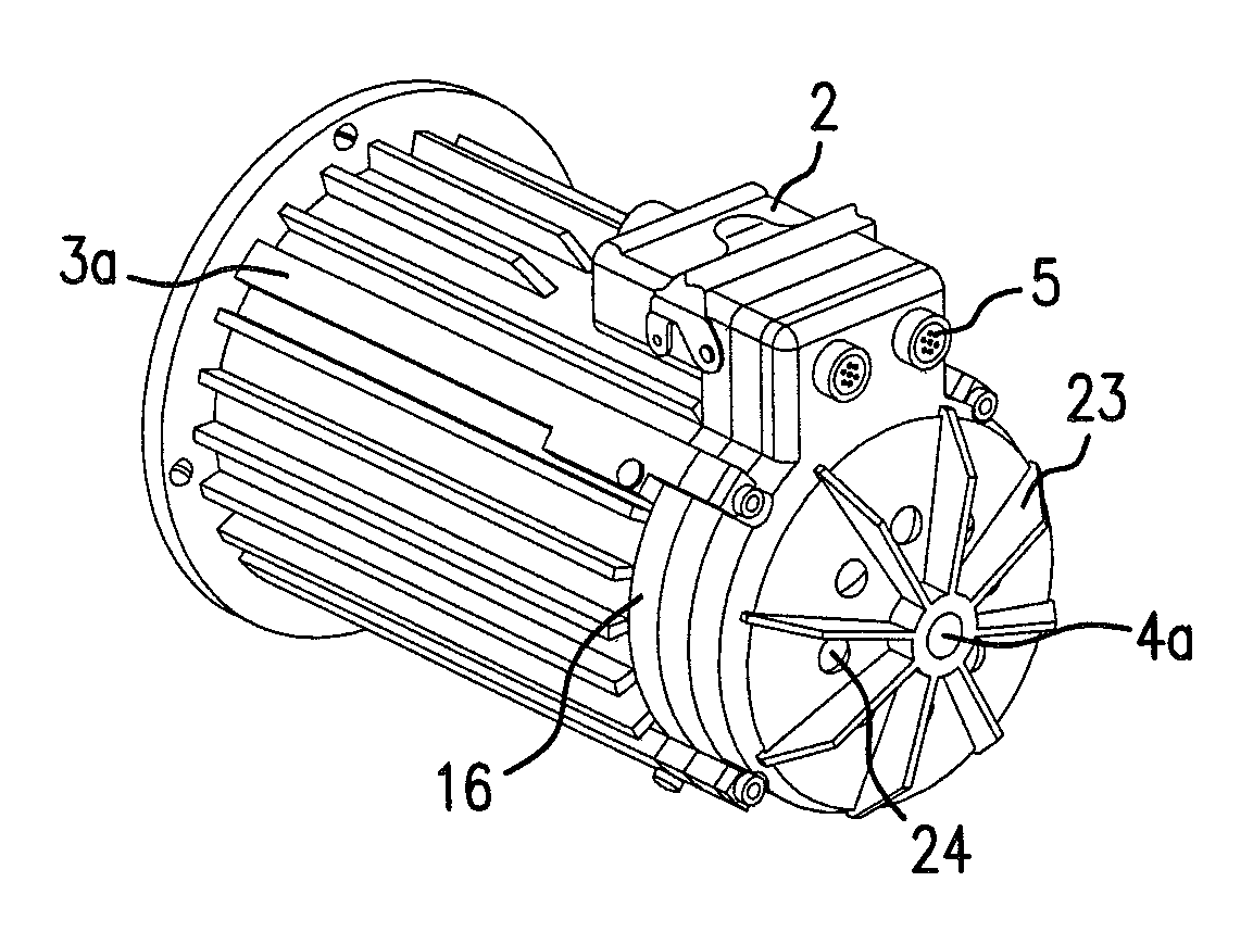
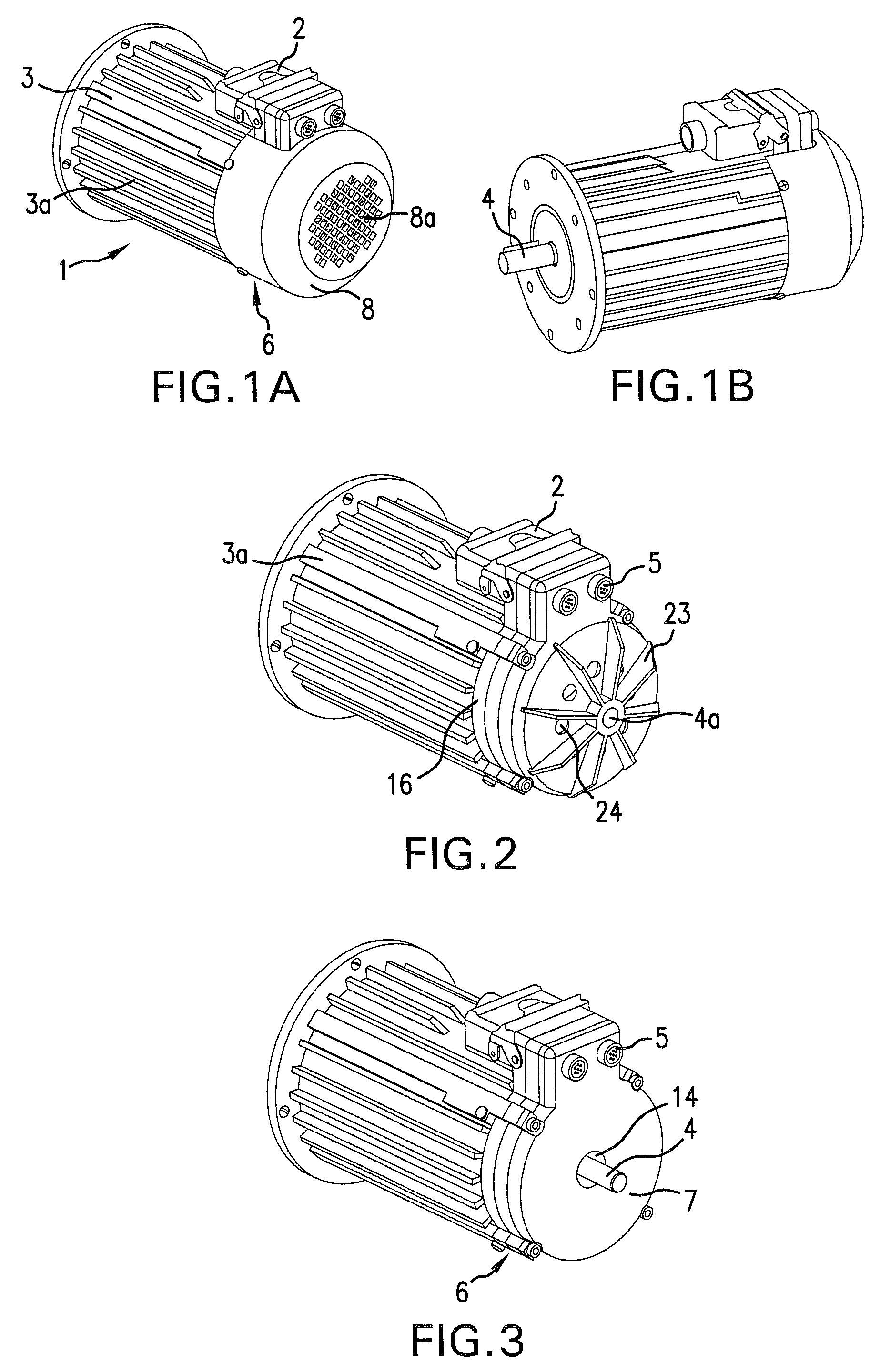
[0050]FIGS. 1a and 1b show an inventive converter motor 1 with a motor housing 3, on which a converter unit 6 is located. Reference numeral 8 indicates a fan hood of the converter unit, which also includes a large number of openings in its back wall 8a, for ventilation.

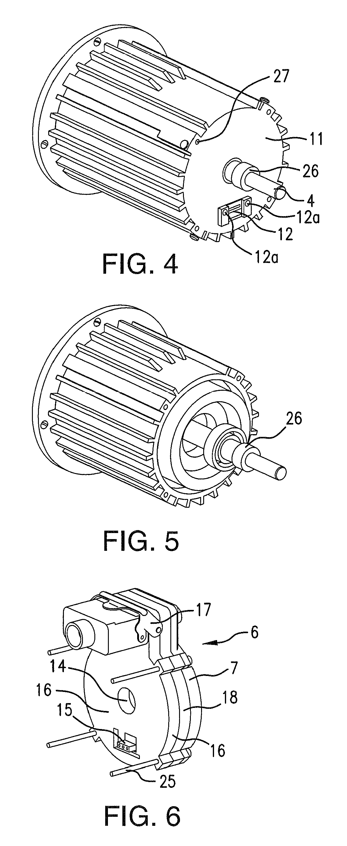
[0051]The mains connection is plugged directly into converter unit 6. A socket (e.g., DESINA) is integrated in the base plate or cover 7 of converter (see FIG. 4). Plug 2 rests on motor 1 in a space-saving manner, thereby minimizing the amount of installation space required for the converter motor. The cable outlet direction of plug 2 may be adapted to the required conditions in any manner necessary by selecting the plug sleeve accordingly.

[0052]The unit composed of motor and converter unit may be designed with degree of protection IP 65. Since the converter unit has a closed housing, the only concern is to ensure that the system have a tight seal in the region of the winding termination, which may be attained, e.g., ...


PUM


Abstract

In a converter motor, the converter unit and the electric motor together form a mechatronic unit. The converter unit is located behind the electric motor and is thermally coupled with the rear bearing shield. The converter unit includes a through hole, through which the rear end of the motor shaft passes. A contactless position detector is located in the region of this through hole.

Description

CROSS-REFERENCE TO A RELATED APPLICATION[0001]The invention described and claimed hereinbelow is also described in German Patent Application DE 10 2006 047 269.1 filed on Oct. 4, 2006. This German Patent Application, whose subject matter is incorporated here by reference, provides the basis for a claim of priority of invention under 35 U.S.C. 119 (a)-(d).BACKGROUND OF THE INVENTION[0002]The present invention relates to an electric motor with a converter unit. Highly diverse types of motors are known from the related art. For example, standard asynchronous motors are the most common types of drives used in industry. These types of motors are inexpensive, very robust, and quiet-running. Asynchronous motors of this type have various disadvantages, however, such as a fixed speed and direction of rotation, and the fact that a separate start-up device is required. In addition, they are inefficient at partial loads, and the cos phi power factor is poor. In addition, active braking cannot b...

Claims


Application Information

Patent Timeline
Patent Type & Authority Patents(United States)
IPC IPC(8): H02K11/00
CPCH02K5/225
Inventor SCHUEREN, VOLKER
Owner ROBERT BOSCH GMBH
Why Eureka
Try Eureka