

Discharge lamp with a holding apparatus for the electrodes
a technology of electrode holding apparatus and discharge lamp, which is applied in the direction of discharge tube/lamp details, gas-filled discharge tubes, solid cathodes, etc., can solve the problems of high-pressure discharge lamps, lamps can be subjected to such shock loads, and sensitive to shock loads, so as to increase the resistance to bursting pressure
- Summary
- Abstract
- Description
- Claims
- Application Information
AI Technical Summary
Benefits of technology
Problems solved by technology
Method used
Image

Examples
Embodiment Construction
[0010]The object of the present invention is therefore to provide a discharge lamp which has such a construction that damage in the event of short-term force effects can at least be reduced.
[0011]This object is achieved by a discharge lamp having the features as claimed in patent Claim 1.
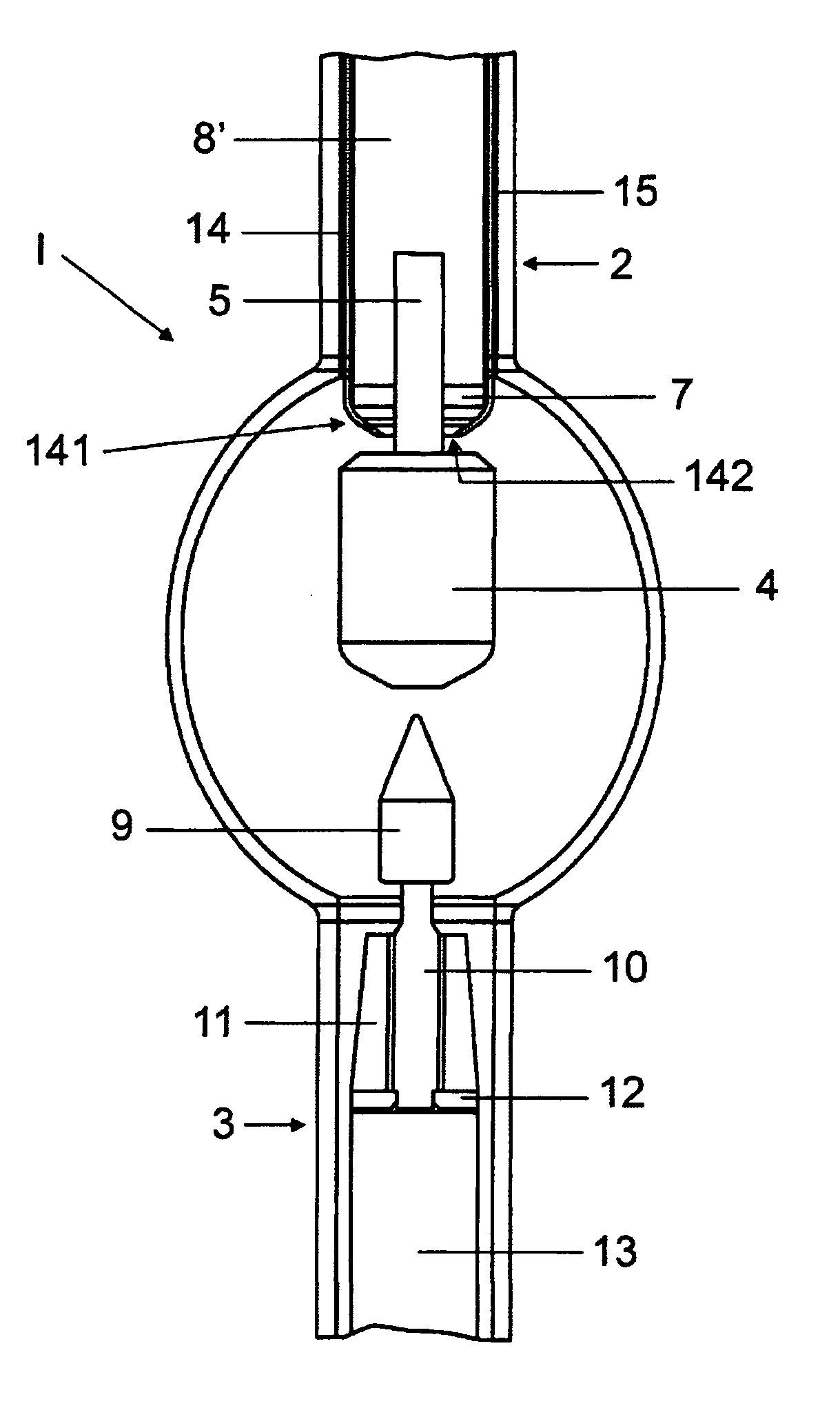
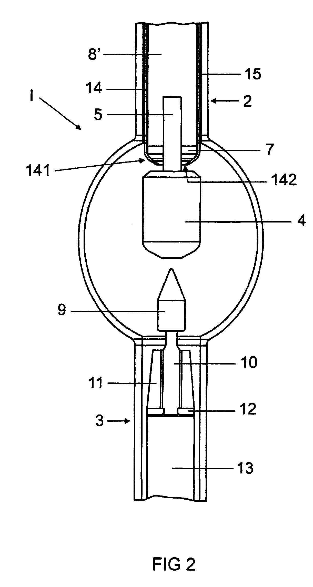
[0012]A discharge lamp according to the invention, in particular a high-pressure discharge lamp, comprises a discharge vessel, which has two preferably diametrically opposite necks, into which in each case one holding rod is fused, at least in regions, and an electrode extending into the discharge vessel is arranged on each holding rod. In each case at least one annular plate is arranged at least on one, preferably on both, of the holding rods so as to at least partially engage around it. At least one of these annular plates is positioned in the discharge vessel. This structural configuration can provide a discharge lamp in which even relatively severe shock loads, as may occur, for example, during ...
PUM
 Abstract
Description
Claims
Application Information