
Evaporative light scattering detector

a detector and light scattering technology, applied in the field of improved evaporative light scattering detectors, can solve the problems of reducing sensitivity, reducing the sensitivity of analyte particles, and reducing the risk of evaporation of relatively volatile analytes

Active Publication Date: 2011-03-22
WATERS TECH CORP
View PDF12 Cites 17 Cited by
  • Summary
  • Abstract
  • Description
  • Claims
  • Application Information

AI Technical Summary

Benefits of technology

It is an object of the present invention to provide ELSD's that are more stable in use than prior types. It is another object to provide ELSD's that have shorter stabilization times than prior types. It is a further object of the invention to provide a methods of operation of ELSD's which result in more stable operation and in a shorter stabilization time than prior methods.
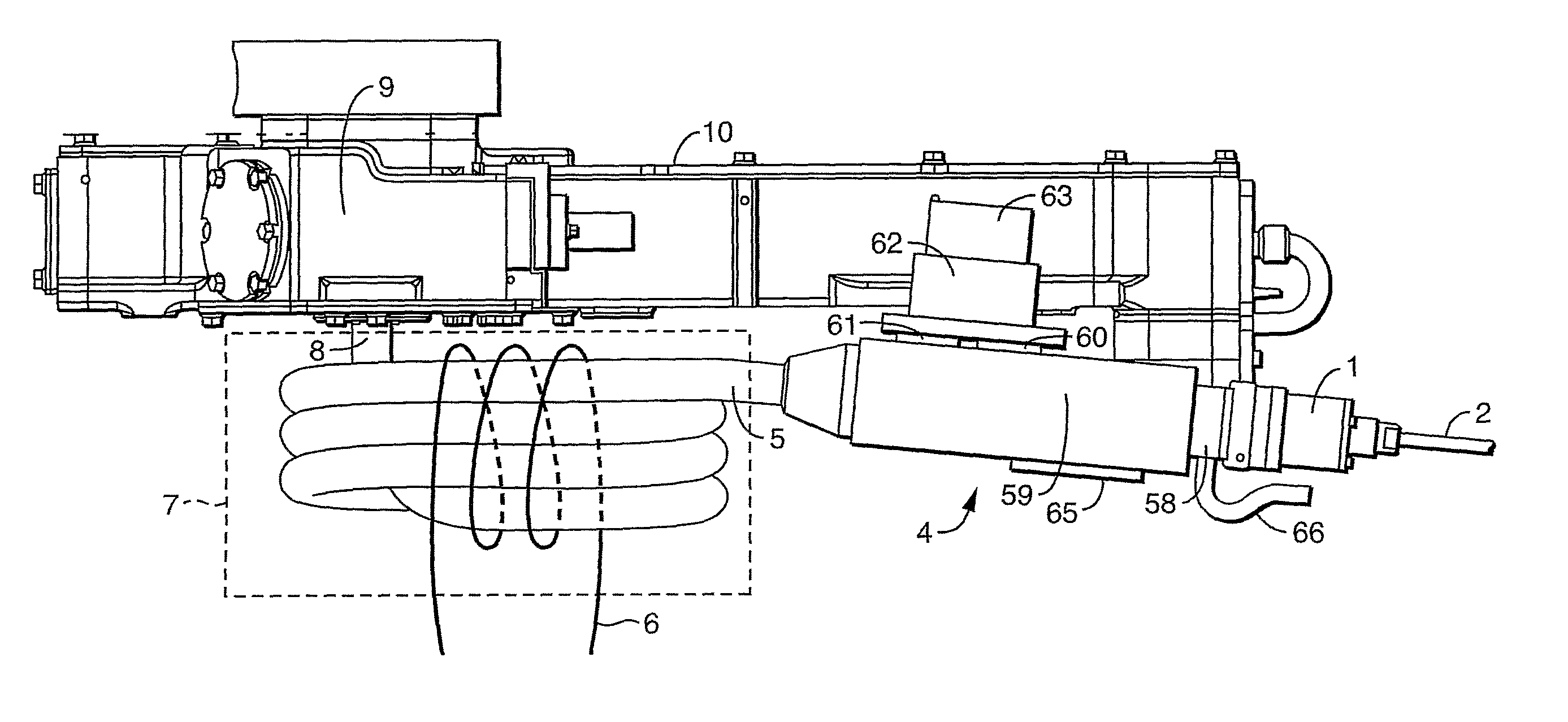
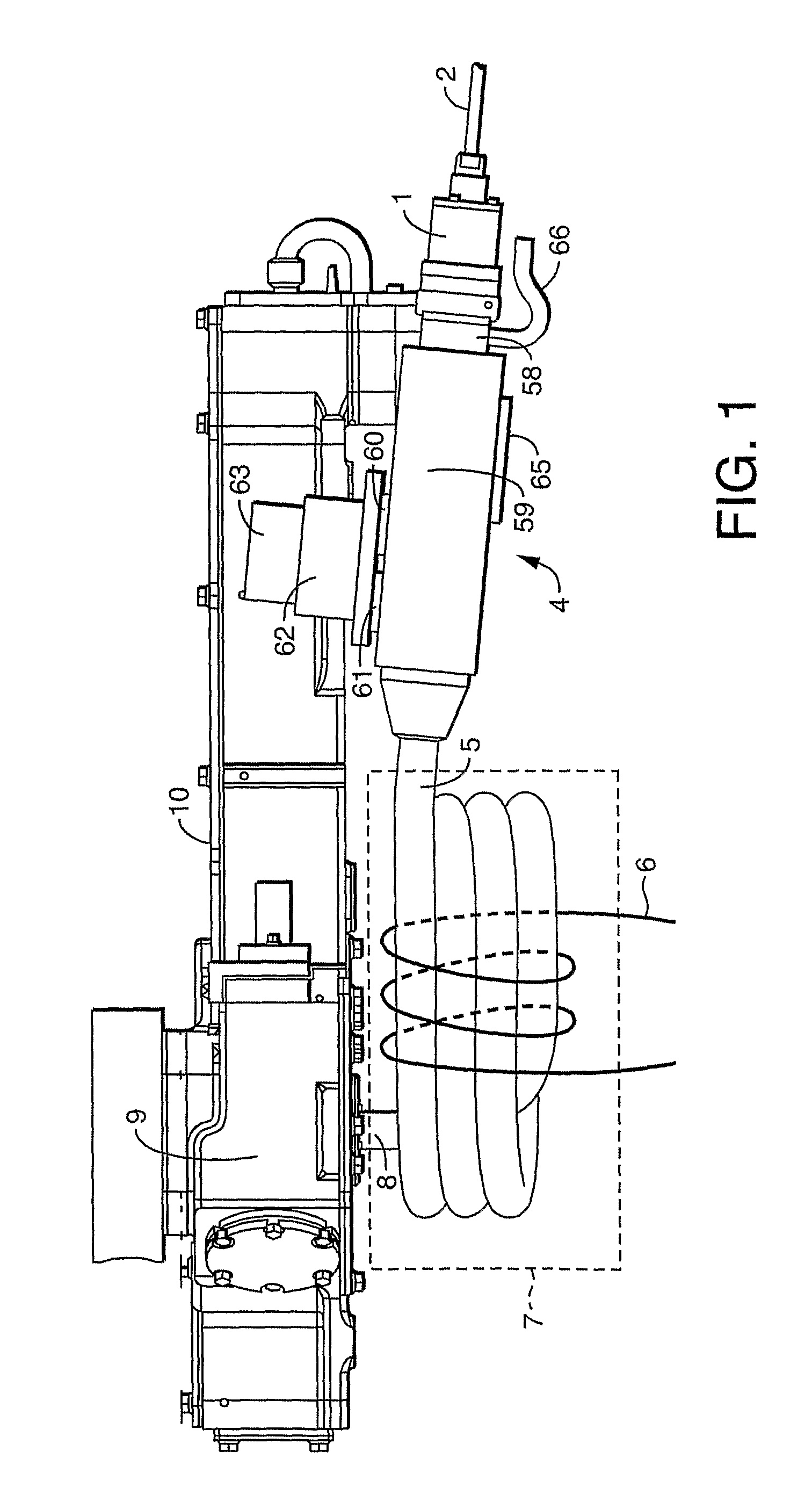
The inventors have found that providing a heat sink in contact with the wall of the nebulizer chamber stabilizes the temperature of the chamber and reduces the time taken for the detector to stabilize before an analysis can be commenced. Pre-cooling the heat sink as described may be carried out before the flow of eluent is started and may further reduce stabilization times and improve stability of the detector. The shortened stabilization times also reduce or eliminate the need to start the flow of eluent through the chromatograph and detector some time before an analysis is commenced, which is characteristic of prior detectors. This reduces waste of solvents.

Problems solved by technology

It is necessary to adjust these latter parameters carefully in order to obtain optimum performance, and the optimum values frequently depend on the mobile phase flow rate and composition, which can cause problems when gradient elution is employed.
Increasing the drift tube temperature can help to evaporate those larger droplets, but risks evaporation of relatively volatile analytes because once the solvent is completely evaporated the temperature of an analyte particle may rise rapidly.
A disadvantage of the additional chamber is, however, the loss of analyte that may be present in the larger droplets that condense in it, reducing sensitivity.
In such applications, the use of a UV-absorbance detector is risky because some of the unknown compounds may fail to be detected even when present in large concentrations, because they have no UV-chromophore.
Unfortunately, prior ELSD's typically require as long as 15-20 minutes to stabilize at the commencement of an analysis, which increases the total analysis time by up to a factor of 10 and renders the use of the ELSD less cost effective in comparison with other detectors, despite its other advantages.

Method used


Image

  • Evaporative light scattering detector
  • Evaporative light scattering detector
  • Evaporative light scattering detector

Examples


working examples

FIGS. 4, 5 and 6 compare the variation in the temperature of the nebulizer chamber with time for two prior ELSD's and an ELSD according to the invention. Referring first to FIG. 4, curves 12, 13 and 14 respectively show the temperature variation observed in the case of prior Waters 2420 detector, a prior Sedex 75 detector (Sedere Inc, 1206, River Road, Cranbury, N.J. 08512-9900, USA) and a Waters 2420 detector fitted with a nebulizer chamber as described above in place of the chamber originally supplied. In each case, the flow of eluent (1.8 ml / minute) was started at time=0 and the temperature of the nebulizer chamber was monitored for a period of three minutes. The drift tube temperature was maintained at 48° C. The composition of the eluent (approximately 90% water, 5% acetonitrile, and 5% of a 1% solution of trifluoroacetic acid in water) remained constant throughout these experiments.

In the case of the modified Waters 2420 detector (curve 14) the chamber was cooled prior to the ...


PUM

PropertyMeasurementUnit
temperatureaaaaaaaaaa

Abstract

Embodiments of the present invention are directed to evaporation light scattering detectors having an evaporative chamber having a wall that is in good thermal contact with a heat sink. The heat has a high thermal mass such that a change in temperature of the wall during an analysis is minimized.

Description

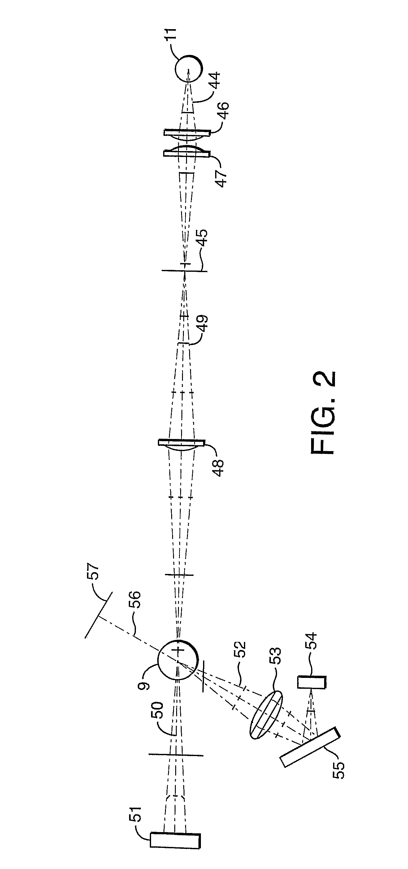
FIELD OF THE INVENTIONThis invention relates to improved evaporative light scattering detectors and methods of operating the same.BACKGROUND OF THE INVENTIONEvaporative Light Scattering Detectors (ELSD) are commonly used in high performance liquid chromatography (HPLC) or supercritical fluid chromatography (SFC) because they are capable of detecting a wider variety of analytes than many other types of chromatographic detectors. Prior ELSD's comprise a nebulizer which receives the eluent from the chromatograph and generates an aerosol comprising droplets of the mobile phase. When an analyte elutes from the chromatograph these droplets will also comprise dissolved or suspended particles of the analyte. The aerosol generated by the nebulizer is passed into a heated desolvation region wherein the mobile phase evaporates leaving dry particles of the analyte. The particles then pass through a light beam and their presence is detected by measuring the scattered light from the beam.The simp...

Claims


Application Information

Patent Timeline
Patent Type & Authority Patents(United States)
IPC IPC(8): G01N21/00
CPCG01N30/74G01N30/84G01N2030/303G01N2030/847G01N21/47
Inventor JARRELL, JOSEPH A.
Owner WATERS TECH CORP
Learn More