Air conditioning device for work vehicle

a technology for working vehicles and air conditioning, which is applied in refrigeration machines, light and heating equipment, transportation and packaging, etc. it can solve the problems of reducing the stability of the vehicle, affecting the maintenance work, so as to facilitate the maintenance work and reduce the center of gravity of the vehicle

Active Publication Date: 2011-03-29
KUBOTA CORP
View PDF47 Cites 35 Cited by
  • Summary
  • Abstract
  • Description
  • Claims
  • Application Information

AI Technical Summary

Benefits of technology

[0005]An object of the present invention is to improve serviceability to the engine and the air conditioning unit as well as stability of the vehicle.
[0007]Since the engine and the air conditioning unit are distributed to the vehicle rear and lower front to the vehicle, this structure facilitates the maintenance work for these parts.
[0008]Also, by locating the air conditioning unit in the lower front of the vehicle, the center of gravity of the vehicle can be lowered as compared with the air conditioning unit provided to the upper portion of the cabin. This also allows supplying of conditioned air not only to the upper body of the operator but also to lower body without the necessity to extend the air conditioning duct from the upper portion to the lower portion of the cabin.

Problems solved by technology

With the first structure, since the engine and the air conditioning unit are located in the limited area in the front of the vehicle, these components tend to overlap or be crammed makes their maintenance difficult.
With the second structure, since the air conditioning unit is located in the upper portion of the cabin, the center of gravity of the vehicle is high, reducing stability of the vehicle.

Method used


Image

  • Air conditioning device for work vehicle
  • Air conditioning device for work vehicle
  • Air conditioning device for work vehicle

Examples


Embodiment Construction

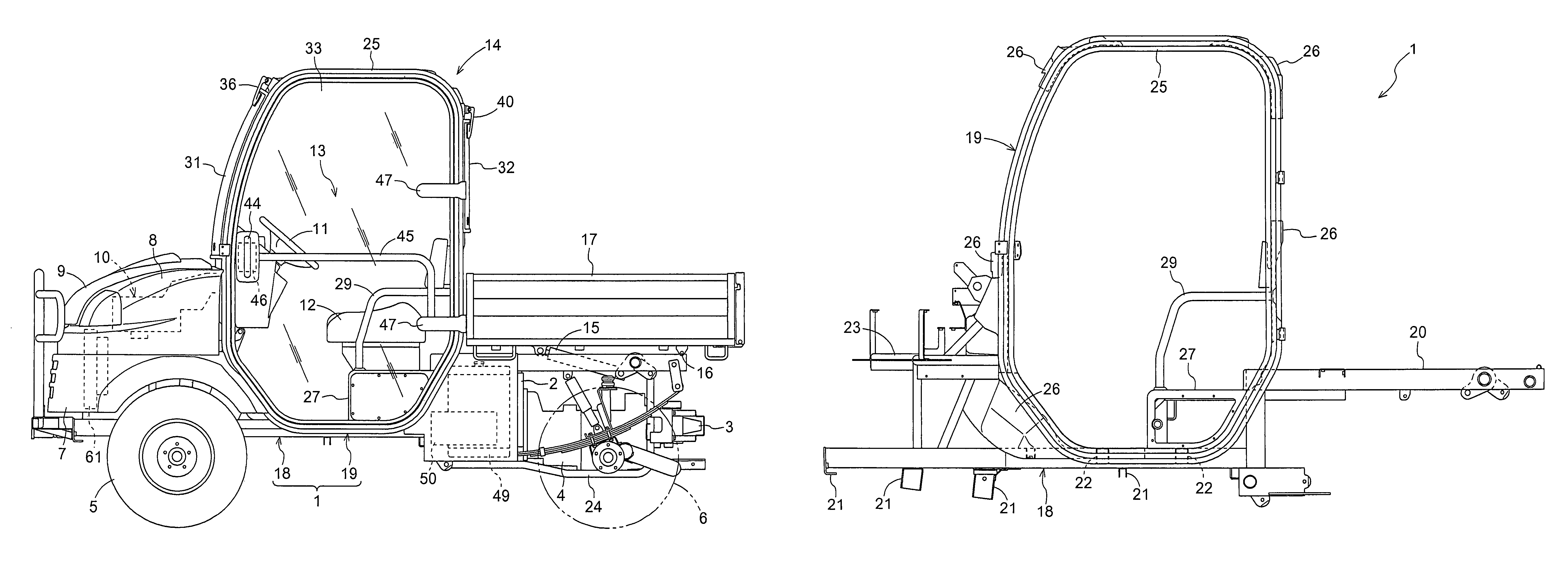
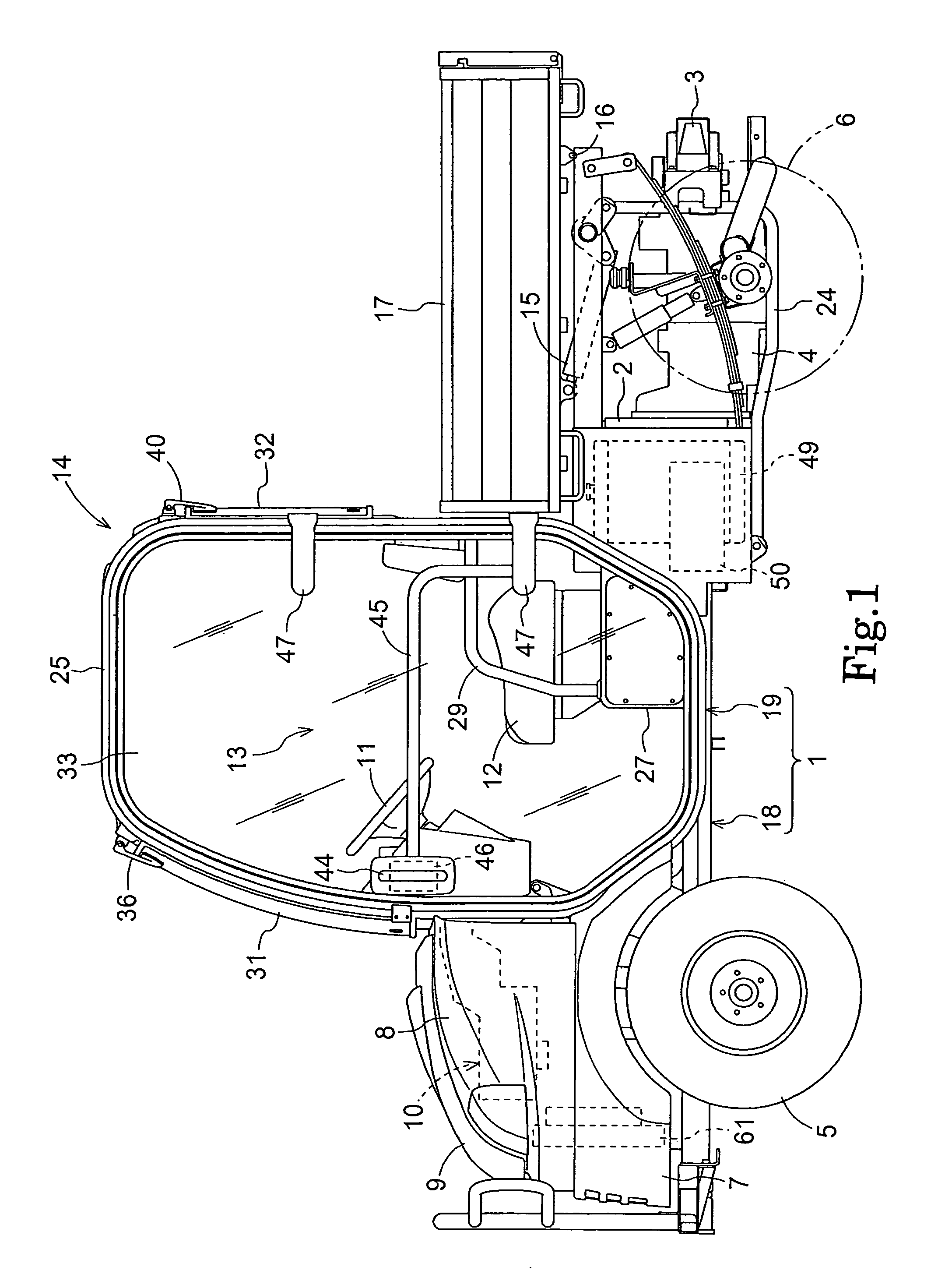
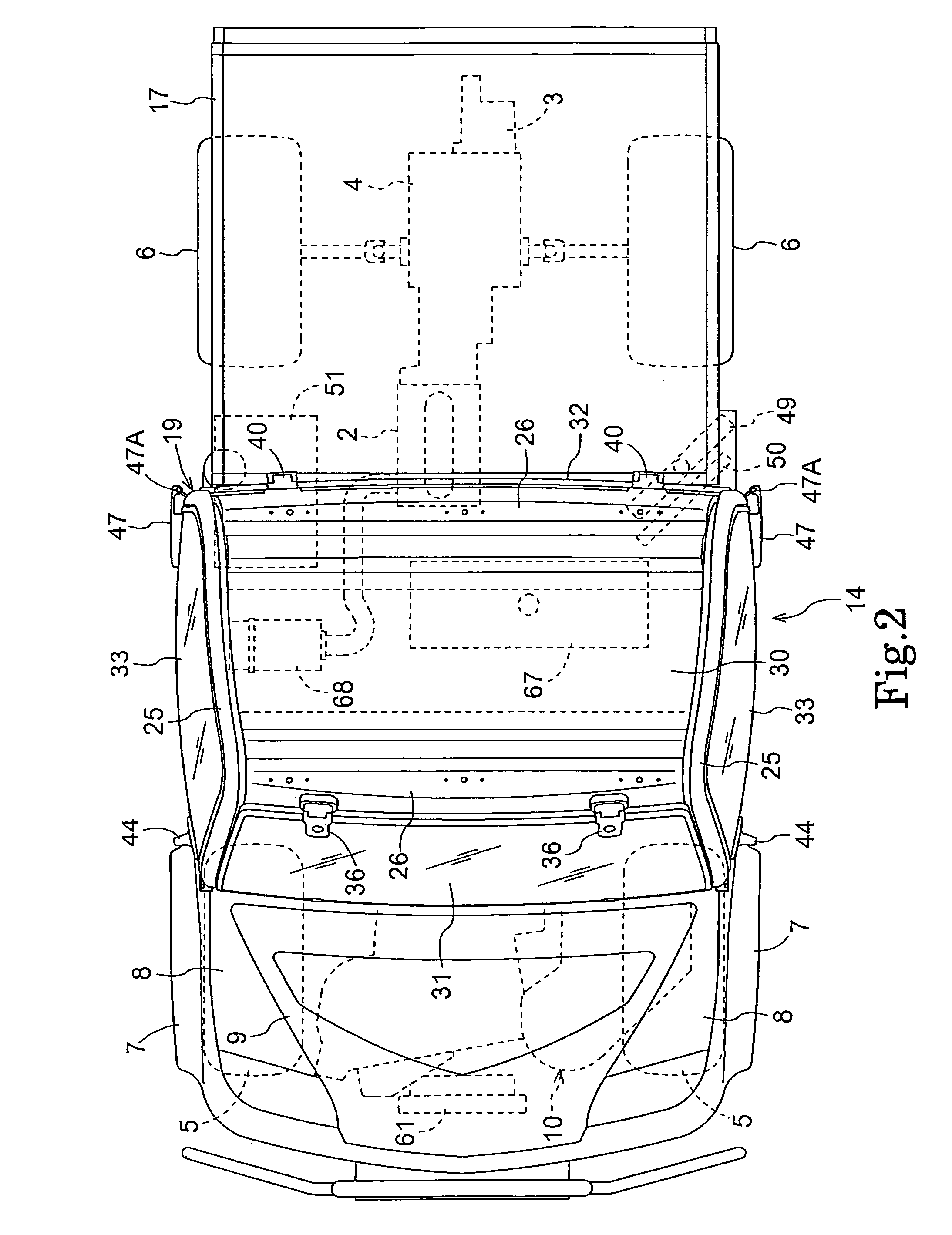
[0019]In FIG. 1, the entire plan view of the work vehicle suitable for transporting articles is shown, while the side view is shown in FIG. 2. This work vehicle is a four-wheel-drive type where the power from the engine 2, which is supported on the vehicle frame 1 via a vibration insulator, is transmitted through the hydrostatic type continuously variable speed change device 3 and the gear type speed change device 4, etc. to a pair of right and left front wheels 5 and the rear wheels 6.

[0020]Provided to the front of the vehicle are lower covering 7 that also functions as a front-wheel fender, the upper cover 8 with an opening in the upper and lateral central region, and a hood 9 that can cover and uncover the opening and that can be opened and closed by pivoting it, etc. The accommodation space formed by them houses the air conditioning unit 10 etc.

[0021]Provided in the longitudinally intermediate region of the vehicle body is the operator's area 13 with the steering wheel 11 for st...


PUM


Abstract

A work vehicle comprises a plurality of wheels; a vehicle body supported by the plurality of wheels and having a cabin, a front half region and a rear half region; an engine located in the rear half region of the vehicle body; and an air conditioning unit located in a lower forward region of the cabin and having an evaporator and a fan.

Description

BACKGROUND OF THE INVENTION[0001]The present invention is directed to an air conditioning device for a work vehicle having a cabin.[0002]Examples of such air conditioning devices for work vehicles include one where an engine and an air conditioning unit are provided to the front of the vehicle body (see, for example, JP2002-96624 (paragraph numbers 0033, 0036, FIGS. 1-4, and 7) and another where the engine is provided to the front of the vehicle and the air conditioning unit located in the upper region of the cabin (see, for example, JP 2005-1537 (paragraph number 0015, FIGS. 1-3).[0003]With the first structure, since the engine and the air conditioning unit are located in the limited area in the front of the vehicle, these components tend to overlap or be crammed makes their maintenance difficult.[0004]With the second structure, since the air conditioning unit is located in the upper portion of the cabin, the center of gravity of the vehicle is high, reducing stability of the vehic...

Claims


Application Information

Patent Timeline
Patent Type & Authority Patents(United States)
IPC IPC(8): B60H1/32F25B27/00B60K11/06B60K11/04
CPCB60H1/00378B60H1/00521B60H1/00535B62D33/06B62D33/0617B60H1/00028B60H1/3204
Inventor NAKAMURA, NORIMI
Owner KUBOTA CORP
Why Eureka
Try Eureka