
Screw

a screw and screw technology, applied in the field of screw, can solve the problems of increasing the amount of labor and time required to drive the screw, and increasing the screwing resistance and drilling torque. achieve the effect of speeding up the screwing and facilitating the attainment of a lower drilling torqu

Inactive Publication Date: 2011-03-29
CHANNG CHIN IND CORP
View PDF6 Cites 6 Cited by
  • Summary
  • Abstract
  • Description
  • Claims
  • Application Information

AI Technical Summary

Benefits of technology

"The present invention provides a screw that can drill through objects with less torque and screw them faster. The screw has a unique design with a tapered shank and two thread segments. The leading segment has a wider thread width and a smooth move through debris, reducing friction and torque. The invention also helps to decrease screwing torque and maintain a better effect at screwing."

Problems solved by technology

However, when driving the screw 1 into an object, debris to be extruded out of a channeled hole acts as a counter-acting force against the driven threads 13, which increases the amount of labor and time required to drive the screw 1.
However, such debris would interfere with the advance of the screw 2 when it turns to immediately surround the shank 22, which may incur a larger drilling torque.
Hence, Phipard's fastener potentially results of a progressive increment of the screwing resistance and drilling torque during the travel of the screw 2 through the workpiece and even causes the destruction of the workpiece 4.
It still fails to overcome the deficiencies of the conventional screw 1.

Method used


Image

  • Screw
  • Screw
  • Screw

Examples


Embodiment Construction

[0021]Before in greater detail, it should note that the like elements are denoted by similar reference numerals throughout the disclosure.

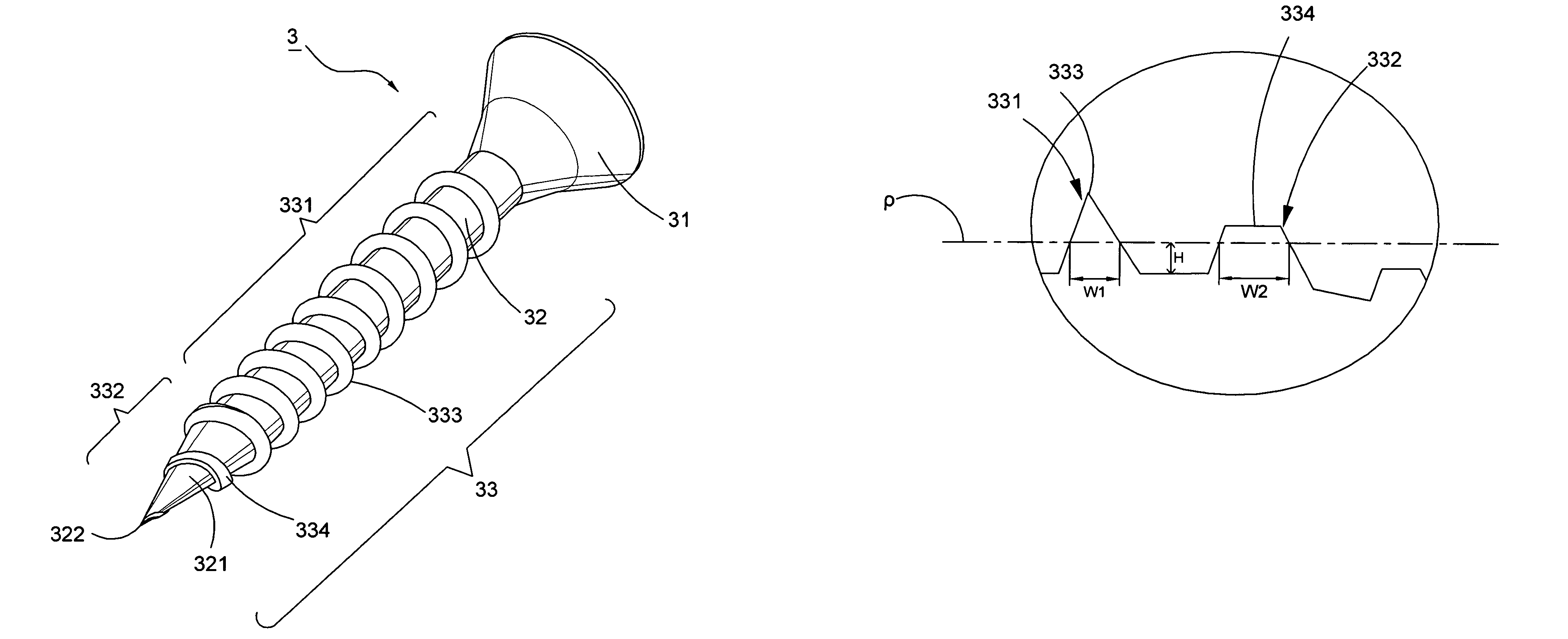
[0022]Referring to FIG. 4, a screw 3 of the first preferred embodiment of the present invention has a head 31, a shank 32 longitudinally extending from the head 31, and a first thread section 33 spirally disposed on shank 32; wherein the head 31 sets a recess thereon (not shown in figures) for being adapted to various types of screwdrivers or relevant tools in conformity with user's demand. It is not restricted to the recess that is a sort of Phillip, slotted, and other different kinds of shapes. Besides, the shank 32 provides with a tip section 321 and terminates at a gimlet tip 322. Further, the first thread section 33 has a trailing thread segment 331 helically disposed on the shank 32 and a leading thread segment 332 spirally defined on the tip section 321. The essential characteristics of the present invention include threads of trailing thre...


PUM

PropertyMeasurementUnit
lengthaaaaaaaaaa
widthaaaaaaaaaa
shapeaaaaaaaaaa

Abstract

The present invention pertains to a screw with a first thread section comprised of a trailing and a leading thread segments respectively spiraled on a shank and a tip section. Distinctly, the leading thread segment defines a plane surface thereon to convergently engage with an adjacently thread peak on the trailing thread segment and further constructs a thread width greater than that of the trailing thread segment while aligning the two thread segments with a correspondent profile thread height. Such configuration of the plane surface accompanies its larger thread width to enlarge a drilling channel and accordingly renders an easy entry of the trailing thread segment into an object with less friction and higher screwing speed. Additionally, the debris is partially removed through the void between the enlarged channel and the trailing thread segment to avoid cracking the object, decrease drilling torque, and enhance the fastening capability.

Description

CROSS-REFERENCE TO RELATED APPLICATION[0001]This application is a continuation-in-part of the U.S. patent application Ser. No. 11 / 585,153, filed on Oct. 24, 2006, now abandoned; the subject matter is incorporated herein by reference in its entirety.BACKGROUND OF THE INVENTION[0002]1. Field of the Invention[0003]The present invention relates to a screw, in particular to a screw with lower screwing torque and higher screwing speed.[0004]2. Description of the Related Art[0005]A conventional screw 1 disclosed in FIG. 1 generally comprises a head 11, a shank 12 extending therefrom, and a set of threads 13 spirally arranged on the shank 12 along a shank axis α. While initially directing the shank 12 toward an object 4 (i.e. chipboard), users impart a torque force upon the head 11 to drive the thread 13 rotarily cutting the object 4 and progressively drill the shank 12 into the object 4. However, when driving the screw 1 into an object, debris to be extruded out of a channeled hole acts as...

Claims


Application Information

Patent Timeline
Patent Type & Authority Patents(United States)
IPC IPC(8): F16B25/00
CPCF16B25/0015F16B25/0047F16B25/0057F16B25/106F16B33/02F16B2033/025
Inventor LIN, CHING-GUEIWU, MAU-CHANG
Owner CHANNG CHIN IND CORP
Learn More