Conical washer spring support

a technology of washer springs and supports, applied in the direction of machine supports, wound springs, other domestic objects, etc., can solve the problems of limiting the placement options of spring supports, difficult installation, and many times less than 14′′ of pde displacement, and achieves cost savings, and reduces the effect of pde displacemen

Inactive Publication Date: 2011-04-05
DISC SPRING TECH
View PDF1 Cites 3 Cited by
  • Summary
  • Abstract
  • Description
  • Claims
  • Application Information

AI Technical Summary

Benefits of technology

[0027]The proposed innovation uses conical springs (e.g. Belleville, etc.) as the deflection devise instead of a conventional helical coil spring. Disc springs have been virtually ignored in pipe support application. Disc springs offer an advantage over helical coil springs in satisfying small displacements in limited space within the piping system. By stacking conical springs and compressing them to a predetermined load, the Conical (Washer) Spring Support / Hanger can effectively maintain support of PDE through an operating displacement in the minimum amount of space. By using conical springs, the height of a typical spring support can be reduced by 30% to 50% for displacements from 0 to ⅝″. This device is also suitable for placement under equipment such as pumps, turbines, compressor base plates, heat exchangers and vessels where a helical coil spring is impractical.
[0042]5) Stacking the conical spring washers in ‘series’ to increase deflection while maintaining a compact design is a great advantage. In contrast, stacking the conical spring washers in ‘parallel’ reduces the amount of deflection but allows for greater loads while shortening the support even more. These combinations offer a wide variety of performance options. Disc springs (conical washers) have, virtually, no fatigue for normal load applications and high cycle life for dynamic load applications.

Problems solved by technology

However, thermal and dynamic displacements in PDE are many times less than ¼″.
The obstructions that occur often limit the placement options for spring supports.
The room for the spring support makes installation a challenge due to restricted space.

Method used


Image

  • Conical washer spring support
  • Conical washer spring support
  • Conical washer spring support

Examples


Embodiment Construction

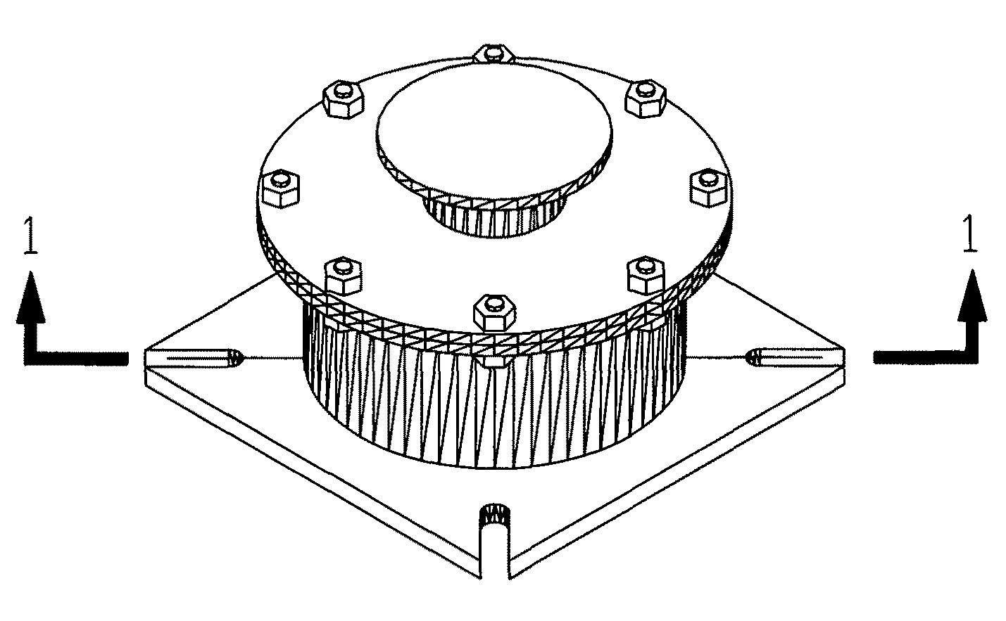
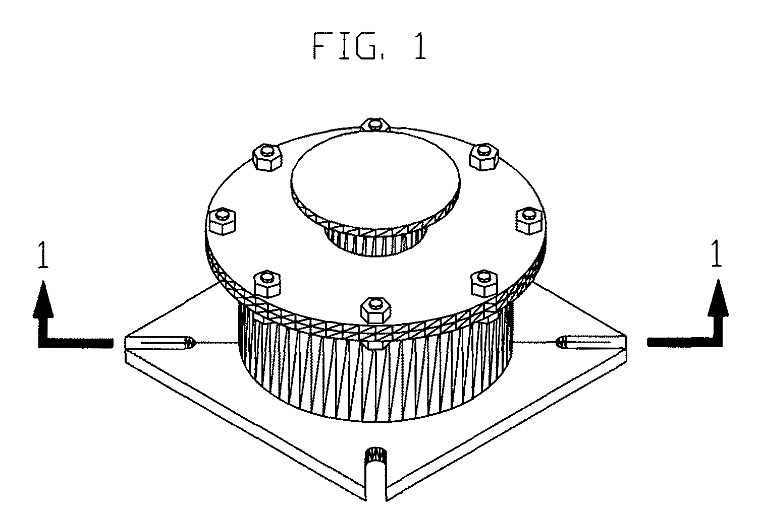
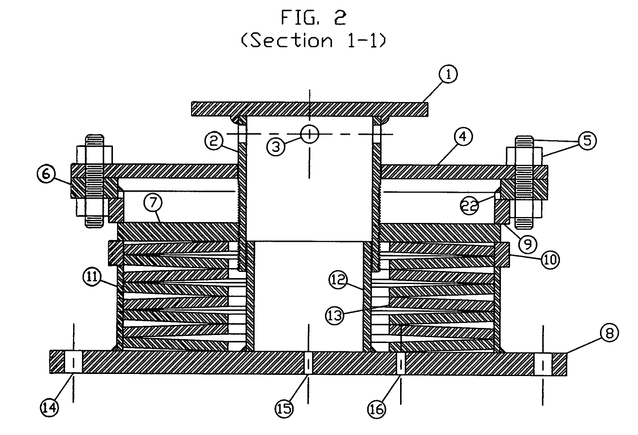
[0053]Referencing FIGS. 1, 2, &3, each drawing is an example of a typical support type of a Conical Washer Spring Support 100. The load flange 1 is a flat disc with a concentric, circular lip 1A welded to the disc's bottom surface about the disc's centerline. As seen in FIG. 2 and FIG. 9, the load flange 1 fits transversely onto the load column 2 and is allowed to rotate freely on top of the load column's top edge 2B. The load flange 1 is guided and maintains its center position on top of the load column 2 by the loose fit between the circular lip's inner surface 1A and load column's top edge, outer surface 2B. The load column 2, assembled vertically, is a piston shaped cylinder machined flat on it's top edge 2B and threaded at its lower end 2A. When assembled, the threaded lower end 2A of the load column 2 engages the load plunger threaded inner diameter 7A, which in turn, is in contact with the top edge of the conical washer(s) 32, shown in FIG. 2. The load plunger 7 is a donut sh...


PUM


Abstract

This invention relates to a support or hanger utilizing a conical spring washer or set of conical spring washer displaying variable load characteristics. When installed, both types (support or hanger) allow for small movements in pipe, ductwork or equipment (PDE), thus, allowing for the thermal growth of PDE. Conventionally, helical coil spring supports are chosen to meet the load capacities of PDE but are reluctantly used because of their large size. By using conical spring washer s, the size of the support is substantially reduced making it a more useable device. A smaller, more compact design proves to increase the support / hanger's application making it more stable to place under piping and even under reciprocating motion equipment like generators and pumps. For small displacements, it is found that this invention behaves in the same manor as a conventional helical coil spring support under the same applied loads.

Description

CROSS-REFERENCE TO RELATED APPLICATIONS[0001]This application claims priority under 35 U.S.C. §119(e) to U.S. Provisional Patent Application Ser. No. 60 / 765,348 entitled Conical Washer Spring Support, filed Feb. 6, 2006. The complete disclosure of that application is herein incorporated by reference for all purposes.[0002]U.S. Patent DocumentsU.S. Pat. No.Issued DateInventorClassification5009386June., 1989Berger248 / 6134627593December, 1986A. J. Salter248 / 5615944288August, 1999Whitney / Birch248 / 0584238102December, 1980C. J. Salter248 / 5434640487February, 1987A. J. Salter248 / 5714206898June, 1980C. J. Salter248 / 5613833194September, 1974A. J. Salter248 / 0546517060February, 2003Z. A. Kemeny267 / 1365564664October, 1996M. Oschwald  248 / 288.515482406January, 1996E. J. Arlt, III  405 / 195.15458313October, 1995R. Tie et al.248 / 6134200256April, 1980P. H. Thiel248 / 5483873079March, 1975F. Kuus267 / 1623856242December, 1974B. D. Cook248 / 0203770232November, 1973J. C. Blake248 / 0213107905October, 1963C. D....

Claims


Application Information

Patent Timeline
Patent Type & Authority Patents(United States)
IPC IPC(8): F16M13/00
CPCF16F3/02F16F1/32
Inventor TAYLOR, III, JAMES OCTAVIUSREDMANN, KLAUS PETERMAKADIA, BHARAT VALLABHDASLEONARDI, KIRK VINCENT
Owner DISC SPRING TECH
Why Eureka
Try Eureka