Image reading device and image forming apparatus

a reading device and image technology, applied in the field of image reading devices, can solve the problems of deterioration in image quality, black shadow formation, undetectable black shadow in the read out image of documents, etc., and achieve the effects of small size, remarkable energy conservation, and not easy to generate variance in illuminance distribution

Inactive Publication Date: 2011-04-05
RICOH KK
View PDF22 Cites 28 Cited by
  • Summary
  • Abstract
  • Description
  • Claims
  • Application Information

AI Technical Summary

Benefits of technology

[0027]The present invention has been accomplished in view of the hitherto unsolved problems of the prior technology and it is an object of the present invention to provide an image reading apparatus and an image forming apparatus which are small-sized and energy-saving by use of a reduced number of light sources, and with which a variance in an illuminance distribution is not easily generated due to a movement (an accompanied vibration or an external vibration) of a document illuminating device included. Compared with a tubular light source, the light source employed is remarkable in energy conservation.

Problems solved by technology

Consequently, the density irregularity is generated partly in the scanned image, which results in deterioration in an image quality.
Here, a problem that needs further considering is that when the illumination fails to reach the entire document to be read out, a black shadow is formed in a read out image of the document.
Consequently, the problem arises that the black shadow undesirably appears in the read out image of the document.
However, unfortunately, the above-mentioned “black shadow” problem is not considered in any of Japanese Patent Application Publication Numbers 2006-67551, 2006-42016, 2005-311662 and 2005-241681.
Therefore, since a distance between the document placing surface and a first mirror needs to be kept adequately, an entire illumination optical system may become large in size.
Although an image reading apparatus is configured with the above consideration, as illustrated in FIGS. 15, 16 and 17, due to respective support structures of respective reflectors, a problem arises that the uniformity of the illuminance distribution deteriorates in the sub-scanning direction.
Consequently, a problem of two adjacent peaks appearing in the illuminance distribution arises, as illustrated in FIG. 16.
However, there are some disadvantages such as the document illuminating device being enlarged or increased in weight.

Method used


Image

  • Image reading device and image forming apparatus
  • Image reading device and image forming apparatus
  • Image reading device and image forming apparatus

Examples


embodiment 1

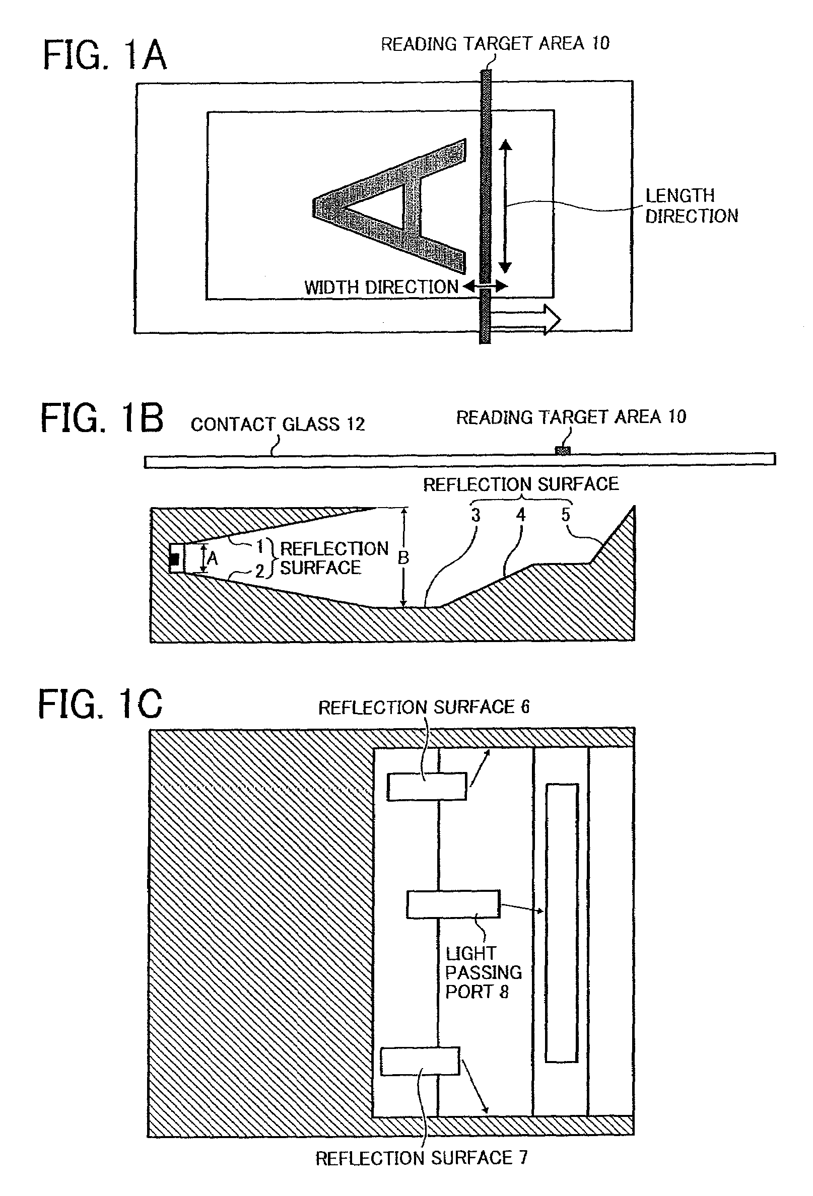
[0079]FIGS. 1A to 1F illustrate an image reading apparatus according to a first embodiment of the present invention.

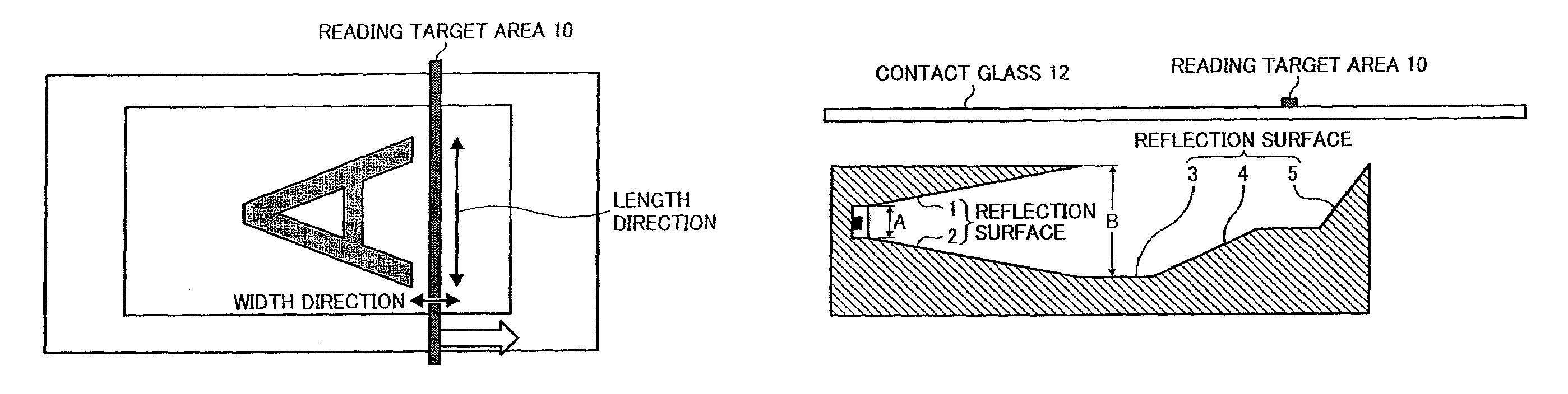
[0080]FIG. 1A illustrates a length direction and a width direction of the reading target area on a document placing surface.

[0081]FIG. 1B is a profile schematic view illustrating a configuration of the document illustrating device including a plurality of white LED light sources and a plurality of reflection surfaces, included in the image reading apparatus of the present invention (for the sake of illustration, a contact glass 12 is not shown).

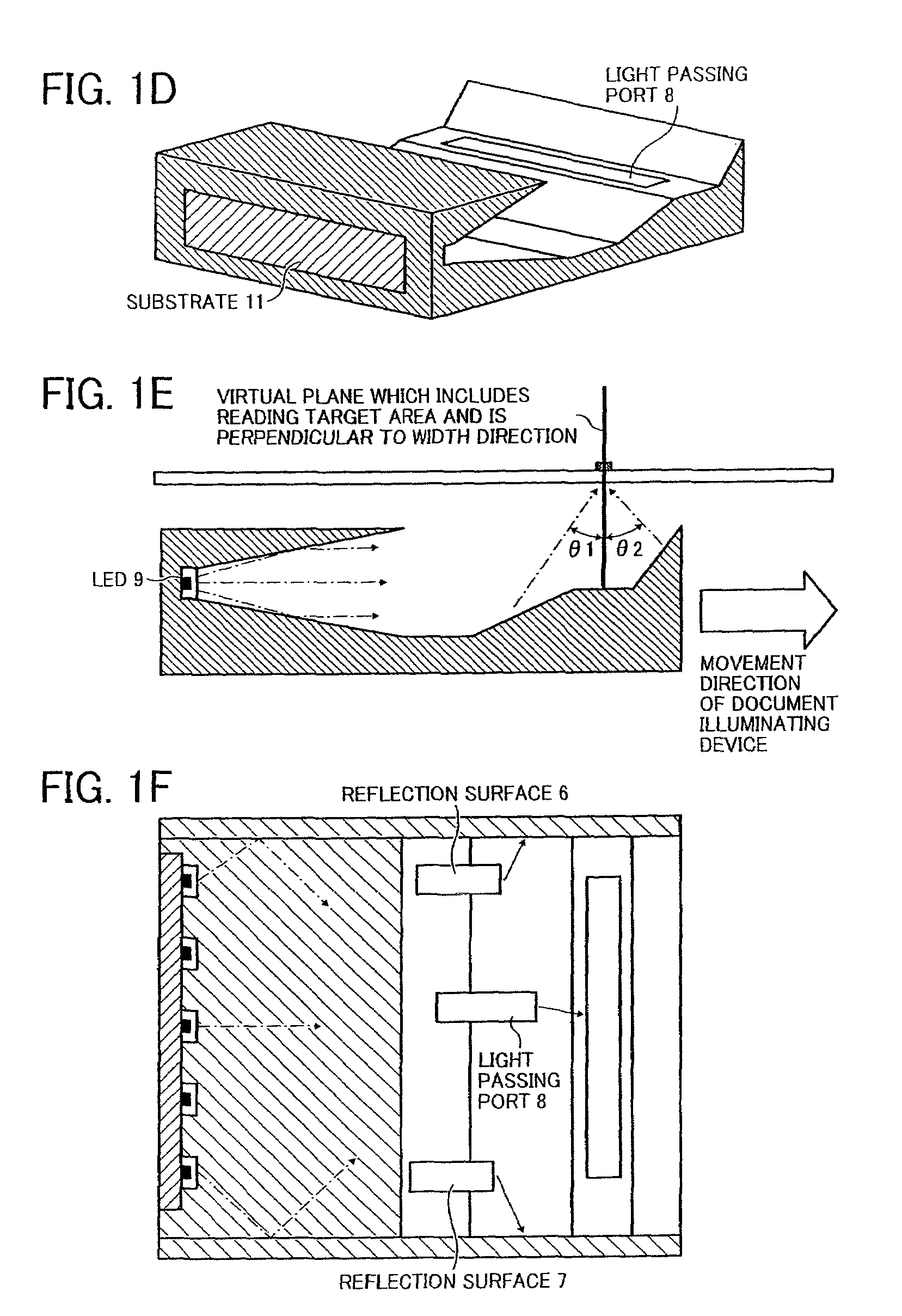
[0082]However, the plurality of reflection surfaces (e.g. reflection surfaces 6 and 7) at both sides of the document illuminating device are omitted in order to clearly illustrate a configuration of the document illuminating device in FIGS. 1B, 1D and 1E.

[0083]Here, light for illumination can either be the light emitted from the plurality of white LEDs or mixed light of light emitted from the plurality of LEDs of two or more col...

embodiment 2

[0098]A second embodiment is concerned with an image reading apparatus including the document illuminating device of the first embodiment.

[0099]FIG. 2 is a profile schematic view of the image reading apparatus according to the second embodiment of the present invention. (However, for the sake of illustration, the contact glass 12 is shown.)

[0100]According to this embodiment, the image reading apparatus is configured to comprise the document illuminating device of the first embodiment, four mirrors 16, a read out lens 13 and a CCD 14. All of these components are fixed respectively via pressing, bonding, screwing or the like to maintain a position thereof unchanged. The image reading apparatus is configured to be moved entirely to read the document.

[0101]As illustrated in FIGS. 1C, 1D and 1F in the first embodiment of the present invention, the light passing port is opened in the document illuminating device. The light from the document placing surface 15 passes the light passing port...

embodiment 3

[0103]A third embodiment is concerned with an image reading apparatus including the document illuminating device of the first embodiment. (However, for the sake of illustration, the contact glass 12 is shown.)

[0104]FIG. 3 is a profile schematic view of the image reading apparatus according to the third embodiment of the present invention.

[0105]According to this embodiment, the image reading apparatus is configured to comprise the document illuminating device of the first embodiment, three mirrors 16a, 16b and 16c, the read out lens 13 and the CCD 14. The document illuminating device and the mirror 16a are moved at a velocity of V; while the mirrors 16b and 16c are moved at a velocity of ½V correspondingly, whereby the document is read.

[0106]In accordance with such a configuration, since an optical path from the document to the CCD 14 is not varied when the document illuminating device or the like is moved, the document can be read.


PUM


Abstract

An image reading apparatus includes a plurality of light sources to illuminate a document; an illumination optical system to guide light to a reading target area having a length and a width; a document illuminating device to illuminate the entire document; an image forming optical system to form an image from light reflected from the document; and a sensor provided in an image forming section of the image forming optical system to read the image of the document. The illumination optical system includes a concentration section to control light diffusion, and a reflection section. The reflection section includes at least two integrally configured reflection surfaces, in which a sine value of an angle of reflected light from at least one reflection surface is positive, while a sine value of an angle of reflected light from the rest of at least one reflection surface is negative.

Description

CROSS-REFERENCE TO THE RELATED APPLICATION[0001]This application is based on and claims the priority benefit of Japanese Patent Application No. 2008-012525, filed on Jan. 23, 2008, the disclosure of which is incorporated herein by reference in its entirety.BACKGROUND OF THE INVENTION[0002]1. Field of the Invention[0003]The present invention relates to an image reading device, particularly to an image reading device employed in a digital copy machine or an image scanner, and an image forming apparatus provided with the image reading device.[0004]2. Description of the Related Art[0005]In recent years, along with the development of light-emitting diodes (hereinafter referred to as LED), the brightness of an LED element has been greatly enhanced. Having advantages such as a long service life, high efficiency, high shock-resistance, monochromatic light emission, etc., the LED is expected to be applied extensively in many illumination-related fields.[0006]For example, the LED is employed ...

Claims


Application Information

Patent Timeline
Patent Type & Authority Patents(United States)
IPC IPC(8): H04N1/04
CPCG03B27/54H04N1/02815H04N1/02865H04N1/0285H04N1/0286H04N1/0284
Inventor TATSUNO, HIBIKISAKURAI, YASUONISHINA, KIICHIROONO, NOBUAKIITOH, MASAHIRO
Owner RICOH KK
Why Eureka
Try Eureka